
From: Steve Cirian
I would recommend buying the Pettit mount that replaces the plastic piece that surrounds the steering wheel and houses the indicator stalk, etc. I found that the A-pillar mount puts the gauge in your line of vision if you mount it at the top of the pillar, and blocks your view of the front fender if you mount it at the bottom of the pillar. I used a Dremel tool and cut out a corner section so it sits lower on the pillar. This worked fine, and the cut corner is hidden so it looks good.
Also, the supplied double-sided tape that holds the A-pillar mount to the pillar did not to stick very well. I have heard from several people that had similar problems, and ended up with their gauges dangling by the vacuum hose / wires. The fix for this is to either get new tape or screw the A-pillar mount to the A-pillar. I won't put holes in the interior of my car, so that's out. I used 3M double-sided tape, and it has not moved since (1.5 years).
On with the instructions:
PARTS:

    - Autometer 2401 gauge
    - Mazdatrix A-pillar mount

ADDITIONAL PARTS:

    - 4 feet of 5/32" vacuum hose
    - 2 hose clamps for 5/32"
    - additional brass fittings to go from the ones that came with the
      Autometer gauge to the 5/32" hose.  (not sure of exact sizes,
      but the packaging said one end was for 1/4" hose (I think that is
      for 1/4" outer diameter (OD) hose, as it fits the 5/32"))
    - Teflon tape (for the threads of the brass fittings)
    - 3M double-sided tape
Note: the tubing that came with the Autometer gauge was about 2 - 3 feet too short to reach where I mounted it at the top of the A-pillar. The additional parts would still be necessary even if the tubing was long enough, as the nipple on the manifold is too big to get the Autometer tubing over. So if you are mounting the gauge on the steering column, you will only need a couple of inches of the 5/32" hose and the brass fittings to server as an adapter.
Gene Kan (genehkan@scam.XCF.Berkeley.EDU) mentioned that you could also use nail polish diluted a little to get the color you want, or if you lose the light bulb condom. This may fade over time.
RSOUS (RSOUS@aol.com)said he used a series 194 bulb, e.g.- 194R is red, from Pep Boys or other auto parts store.
I then used a fine-tipped permanent black marker and colored in the outside of the chrome ring, reducing the chrome showing on the ring to that of the stock gauges. (This looks a lot better than it sounds - the ring has a groove in it that guides the marker around in a perfect circle. Plus you could use paint remover to get the marker off if it doesn't look good.)
You will have to do a minor amount of opening up the hole in the Mazdatrix
mount to get the gauge to fit into the hole. The A-pillar mount has a hole
that will accept 2" or 2-1/16" gauges. The Autometer fits this, but is a
little large, so I used a utility knife and shaved very small amounts out
of the hole until the gauge fit in with a reasonable amount of force. You
don't want the gauge to be loose in the hole, but too tight and the mount
may break if you really force it in.
I wired the gauge light in parallel with the ash tray light. e.g.- each
wire on the gauge goes to a different wire on the ash tray. If you had tried
to wire it to only one of the ash tray wires, this would result in a serial
connection. People have reported that this causes the light to brighten when
the dash lights are dimmed. Credits to Martin Crane and David Beale for
pointing out that this is not immediately obvious.
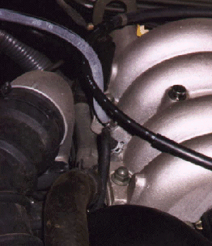
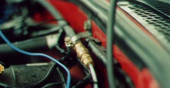
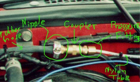
The following photos show the connection between the rubber hose and the vinyl tubing that comes with the gauge (courtesy of Carlton Klein (cklein@g2x.com)):
Credits go to Trixie, Trev, David L., and those mentioned above, and I am probably missing a few folks. I read their posts before doing my install, and they helped a great deal.
_____________
From: mazdarx7@tiac.net (John Levy)
Date: Thu, 16 May 1996 11:09:59 -0400
In answer to:
>Anyways, the question is how/where do I run the
>hose through the firewall to get to the A-pillar mount
>that I have purchased??
Take off the driver's side front tire. Then carefully remove the screws and plastic mollys that are holding the black wheel well in place. If you work carefully you only have to remove those on the half closest to the driver. Now carefully pull this part of the black material away from the fire wall. Underneath you will find a black rubber cap. Pull it off and you have access through the firewall. The vacuum line should be brought off the manifold into the wheel well through a puncture hole you make in the rubber cap and then into the car entering to the side of the fuse box at the driver's feet. In order to replace the rubber cap you may have to first remove the nylon insert which is in the firewall. This is unusual in that it is removed by lifting up on a catch and then pulling on the two halves toward you almost as if you were braking the circumference. Hope this helps.
__________________
Date: Sun, 30 Nov 1997 14:23:30 -0800
From: "Jim LaBreck (ECA)" (a-jimlab@microsoft.com)
(Ed;'s note: Jim posted a review of his GReddy gauge, and I included the parts relevant to installation below. --Steve)
Wiring:
Red wire        -       12V+, ignition switched
Black           -       12V-, ground
Orange          -       12V+, constant
White           -       12V+, illumination
Yellow          -       12V-, output for over-boost warning
Installation was a breeze, cutting the vaccum hose that previously went to my AutoMeter gauge and attaching it to the sending unit that comes with the GReddy gauge. The wiring harness for the gauge itself ran down the gap at the driver's edge of the dash, and then it and the wiring for the sending unit were run along the underside of the dash to the radio area. I tapped 12V+ switched, the illumination circuit (which the AutoMeter was wired to in parallel, allowing it to dim... this gauge doesn't dim and I don't see a simple solution), 12V+ constant, and moved the ground from the illumination circuit to stereo ground. Plugged everything into the control box and it worked.
________________
I have not had this problem with mine (from Mazdatrix), but here is some info on how to solve a problem with the needle bouncing. --Steve
Date: Thu, 4 Dec 1997 09:07:27 -0500
From: Rob Robinette (robinett@postoffice.dca.net)
I have an A pillar mounted AutoMeter boost gauge that I got from Pettit in 93. By their design it is bolted directly to the pillar and I've always had a problem with vibration causing the needle to bounce (vibrate) a lot. I could even hear the needle bouncing around. Yesterday I unbolted the gauge and used a 1/4 inch rubber grommet between the cup and the pillar as a washer to reduce the vibration. It works great, at least an 80% reduction in needle bounce.
________________
From: Wael El-Dasher (wael.el-dasher@efini.net)
Date: April 7, 2000
The Autometer condoms are large, if your gauge uses smaller bulbs, don't waste your time with nail polish because in 2 months it will dry up and a new coating is needed...but VDO makes smaller condoms. I used them on the Blitz gauges and they are a little darker than OEM but work much better than nail polish...anyway the VDO part number is 600853 (light diffuser red 9/32" dia.)
________________
Date: Tue, 24 Feb 98 10:52:52 +0000
From: "RP Sommers" (r.p.sommers@x400.icl.co.uk)
If your boost gauge rises too slowly it could mean the gauge is over-damped. Some gauges have a tiny screw in the brass input fitting to restrict air flow and thus damp down the movement. The effect is easily seen by removing the screw, which causes the needle to show every vacuum pulse and generally wobble around a lot. If your gauge has such a screw, unscrew it until the needle starts to wobble, then turn it back a tad.
________________
From: David Beale
Date: April 5, 2000
One other thing. If you use both wires from the lighter lamp or glove box lamp, be very careful not to ground one. This will be dangerous and potentially expensive. You can burn out the light control pot., the wires, or if lucky just the fuse. If your gauge has one side of the lamp connected to the case (normally done) and if the case is metal it's a good idea to insulate it with heatshrink or tape, and use plastic to mount it (plastic gauge pod, or plastic sheet if you make your own).

[Mail me] [To Lightning home] [To my home page] [Copyright Notice]