Bushing Install - Rear Suspension Kit

Last updated: February 5, 2001


Installation of your Unobtainium Motorsports rear bushing kit is fairly straight forward. Please refer to the illustrations above and in the body of these instructions in order to simplify the identification of the parts in your kit and their installed locations.

1. Refer to the Mazda 3rd generation RX-7 Shop Manual for instructions on the removal and replacement of the rear suspension components. Torque values for the suspension bolts will be listed in the shop manual. Please follow those instructions precisely to 
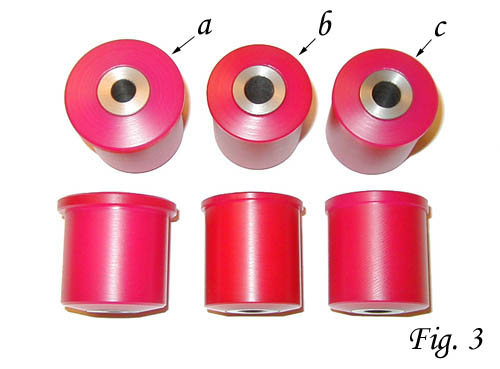
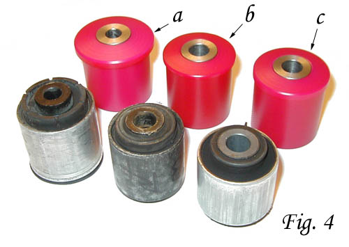
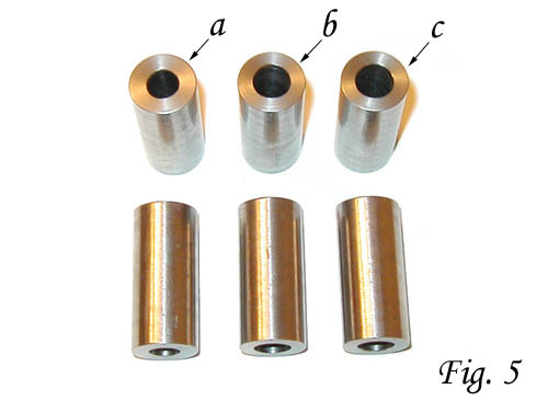
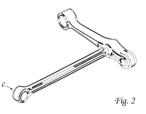
ensure correct installation of the suspension components.

2. Once the suspension components have been removed from the car, use a hydraulic press to press out the OEM rubber bushings, or have a machine or suspension shop perform this service for you. Please note that it is not necessary to remove the rear lower control arms from the car to complete the installation of your bushing kit. Only the rear upper control arms and rear trailing arms need to be removed.

IMPORTANT: Do NOT remove a bushing in any location other than those indicated by the labels a, b, or c in Fig. 1 and Fig. 2 above. The rear suspension kit bushings are intended to replace ONLY the bushings indicated by those labels. The other bushings in the rear suspension are "pillow ball" bushings, and they provide a much wider orbital range of motion than a standard bushing. The pillow ball bushings are metal-on-metal by construction, so replacing them is unnecessary unless they are excessively worn, and would not improve the function or stiffness of the suspension. In the event that they are excessively worn, please have them replaced with OEM Mazda parts.

3. The center pins in your kit are intended to be a loose fit and will not be installed with the nylon bushings when they are pressed into the suspension components. Set the center pins aside, since they will not be installed until you are ready to replace the suspension components on the vehicle.

4. There are three different styles of bushings in the rear bushing kit, as shown in Fig. 3 below. Although the height of the bushings in the kit are very similar, the four that are noticeably largest in diameter are for the rear upper control arms, and are labeled a in Fig. 3 and Fig. 4 below. Their position is illustrated in Fig. 1 above as a, two bushings for each upper control arm. Press these bushings into the upper control arms in position a in the direction of the arrows in Fig. 1 above, so that the flanged ends of the bushings face outward, in the opposite directions of the arrows.


5. Of the four remaining bushings, two are a fraction of an inch shorter than the other two, but they can be more easily identified by the thickness of the bushing flange. As is evident in Fig. 3 above, the bushing labeled b has a noticeably thinner flange than the bushing labeled c. These bushings (labeled b in Fig. 3) are intended to be placed in position b in the upper control arm illustrated in Fig. 1 above, one on each side of the car. Press the nylon bushing into the control arm in position b in the direction of the arrow, with the flanged end of the bushing facing outward from the control arm in the opposite direction of the arrow.

NOTE: The illustration in Fig. 1 above represents the upper control arm from the driver's side of the car. On the passenger side upper control arm, the strut mount bushing should be pressed into the control arm from the opposite side to ensure that on each side of the car, the flanged ends of the strut mount bushings will be facing the front of the vehicle when the control arms are reinstalled.

As shown in Fig. 4 above, the OEM rear strut bushing that bushing b replaces is different in appearance and construction than the OEM bushing c, which comes from the front of the trailing arm.

6. The two remaining bushings with thicker flanges (labeled c in Fig. 3 and Fig. 4 above) are intended to be placed in position c in Fig. 2 above, one on each side of the car, in the front of the trailing arm. Press the nylon bushing into the trailing arm in position c in the direction of the arrow, with the flanged end facing in the opposite direction of the arrow.

NOTE: When the trailing arms are reinstalled, the flanged ends of the trailing arm bushings should be on the side of the trailing arm which faces towards the center of the car.

7. Once all eight bushings have been installed, follow the Mazda Shop Manual instructions for replacement of the rear suspension components. Before installing the bolts which hold the control arms and trailing arms on the car, coat the outside surface of the stainless steel center pins (shown in Fig. 5 below) with anti-seize lubricant, and slide them into the centers of the appropriate nylon bushings, wiping off any excess. Again, the center pins are designed to be a loose fit and should slide and rotate freely within the nylon bushings.

The four pins with the smallest center holes (labeled a in Fig. 5 below) are intended to be installed in the bushings in position a illustrated in Fig. 1 above, two per control arm. The remaining four pins have identically sized center holes, so the best way to determine the appropriate locations of these pins is to place all four in a row, standing on end, and touching each other. Two will be slightly (approximately 0.02") but noticeably shorter, and you can determine this by feel, by laying a straight edge on top of the row of pins, or with a set of calipers or another measuring device.

The two shortest pins are intended to be installed with the bushings b, in the position shown in Fig. 1 above, one per control arm. The two longer pins are intended to be installed in the bushings in position c in Fig. 2 above, one per trailing arm.

NOTE: If the center pins for your bushing kits have been inadvertantly mixed together, the front kit bushings can be identified by eliminating the four largest and four smallest pins. Use the information in Step 7 as your guide to identify the remaining pins. If you purchased differential bushings also, the pins for those bushings will be identical to the pins labeled b in Fig. 5 below, intended for the reart strut mounts. After eliminating the four pins with the smallest center holes (a below), there will be two slightly longer pins in the remaining six. Those two are the trailing arm bushings pins (c below), and the four that remain are for the strut mount bushings (2) and the differential bushings (2).


8. Once the center pins are installed in the nylon bushings, you can reinstall the control arms and trailing arms on the car. It is your choice whether or not to coat the bearing surface (non-threaded area) of each suspension bolt which passes through a stainless steel center pin with anti-seize lubricant. While this step is not absolutely necessary, we do recommend it. Install the bolts which hold the control arms and trailing arms to the car following Mazda's torque specifications precisely to ensure a correct installation.

9. Complete the reinstallation of the rear suspension components following the Mazda Shop Manual instructions. Once installation is complete, we highly recommend that you have the car realigned by a professional suspension shop in order to ensure that your suspension geometry is correct.

10. Congratulations! You now have the highest performance rear suspension bushings money can buy on your RX-7, and you should feel a night-and-day difference in the reaction of the car to variances in road surfaces when compared to the OEM rubber bushings.


Unobtanium Logo

Note: This page reproduced with the kind permission of Unobtanium Motorsports.

THE LEGAL STUFF: Unobtainium Motorsports products are intended for off-road use ONLY. Unobtainium Motorsports makes no claims as to the legality of use of these products on a licensed vehicle used on public roads or highways. Unobtainium Motorsports is not responsible for any damage to the vehicle caused by improper installation or improper use of the product or vehicle by the customer or any other party. Damage to the product caused by improper installation or use is not covered by any warranty, either express or implied. Product warranty is limited to manufacturing defects only. Unobtainium Motorsports will replace any defective product at our discretion, once the part has been received and inspected, and the cause of the failure has been determined to be a manufacturing defect.

Unobtainium Motorsports HIGHLY recommends that our products be installed only by trained professionals, and especially with any suspension modifications, that the vehicle manufacturer's service procedures and recommended torque figures be strictly adhered to. In addition, we recommend that the vehicle's alignment be checked and corrected, if necessary, after removal or replacement of any suspension related components. And finally, we highly recommend that any components removed from the vehicle be inspected by a professional service representative prior to being replaced, and if any component or fastener is found to be damaged or substandard in any way, that it be replaced immediately with a new part. Failure to follow these recommendations may result in loss of property or serious injury.


All images and information contained on this site are copyrighted.
Use without the express consent of Unobtainium Motorsports is prohibited.

[ Mail me ] [ To RX-7 Files home page ] [ To my home page ] [ Copyright Notice ]