
Date: Tue, 03 Mar 1998 23:38:41 -0800
From: Daegal Benedetto (dae@ix.netcom.com)
There was a thread on this subject last fall and everyone said they have never had the fans come on by themselves after shutting off the car.
However, there is a way to test the circuitry, (and that leads to a way to make a fan timer). There is a single black wire (with connector) coming out of the ECU that is not attached to anything. To test the fans you need to attach this wire to ground for two minutes while the car is running. With the wire still grounded, turn the car off and the fans will stay on. After 30 seconds, un-ground the wire and the fans switch to low speed. The fans stay on for ten minutes.
The ECU is down in the passenger side foot well. You need to pop off the door sill trim and then pop up and remove all the fasteners holding the foot well panel. Best to go slow with this as the plastic stuff will crack easily. Once the panel is removed you can see the ECU mounted to the chassis. The test lead on mine was just hanging there, toward the front, but I remember someone saying they had to remove the ECU from its mount to get it. The lead is black and has a female spade connector on it. You should test the circuit first to be sure it works. I used a male spade connector end and an alligator clip test wire. Connect it to ground for a little more than 2 minutes while the car is running. Turn the car all the way off and the fans should be running. After 30 seconds disconnect the wire from ground and the fans should switch to low speed and stay on for 10 minutes (it's timed not temp controlled).
I ended up installing a stock foglamp switch in one of the blank switch holes on the center console. (Almost any switch will work, doesn't have to be the Mazda foglamp switch at $50.) I ran one wire from the switch to the ECU test lead and the other to ground. I just engage the switch 2 minutes before I turn the car off if I want the fans to run after.
> How did you route the switch wire from the console to
>the ECU without having to pull up any extra covers or mats,
>etc.?
I didn't. Besides the foot well cover, you have to pop up the center console to mount the switch. I used in-line spade connectors at the switch end and ran 2 twelve gauge wires from the switch, under the center dash, up over the foot well behind the dash under the glove box and down into the ECU area. At the ECU end I used a male spade connector for the test lead and a ring connector which I mounted with another ground wire on the door side of the ECU.
I've had this hooked up since last September. I don't know if it cools the engine off any faster but I can tell you that the engine compartment does cool off faster which can't be bad for all the plastic and rubber in there. I only use it when it seems appropriate but have not seen any affect whatsoever on the battery.
Don't ground the wire all the time as the fans will run all the time. Be sure to allow for a cool down for the oil in the turbos.
_________________
Date: Tue, 5 May 1998 08:48:29 -0400
From: "Houseman, Carl W. x1323" (CHOUSEMAN@genicom.com)
>Is the "cooling fan control module" the small black plastic box?
Yes, it's the black plastic box mounted behind the ECU.
_________________
Date: Tue, 10 Mar 1998 10:06:13 -0500
From: Rippin (rippin@pottsville.infi.net)
It works, I just hooked everything up yesterday and the fans work exactly as you said!! Only one thing, my wire was behind the CPU and it was Black and Greenish/Yellow-striped, however it was the only loose one and it controlled the fan relays, I could hear it clicking them when I had the key on all the way without starting.
_________________
Date: Mon, 20 Jul 1998 22:57:14 -0400
From: Kevin Kieffer (kkief@erols.com)
First, on finding the wire. Some people said theirs was hanging there, but mine was behind the PCME. Unbolt the three bolts (2 on bottom, one on top-right) and pull the PCME away from the panel. Behind it, the small black box is the fan control module. It has one harness coming out with 5 wires. One of them is a black/yellow. Follow that down and you should find a loose black/yellow wire. At the end is a black plastic harness, which shields a female spade connector.
If you mount a switch on the center console, you can run the ground to any of the bolts there--no need to ground it at the PCME.
In a nutshell, here is how the fans work: There are 4 relays. Fans are wired in parallel, so speeds are same for both. Relays 2&4 operate in parallel, too.
When the relays come on:
How fan speed affected by relays:
Other facts:
So there are several permutations depending on what the driver does and the state of the car.
_______________
Date: Thu, 30 Jul 1998 23:09:29 -0400
From: Kevin Kieffer (kkief@erols.com)
I created a quick web page that contains some information about how the fans are controlled and what the fan mod actually does (along with instructions on how to force the fans into different speeds).
Go to: fan mod.
_______________
Date: Thu, 30 Jul 1998 10:06:04 -0700
From: "Kinports, Robert" (RBK1@pge.com)
As promised, last weekend I used thermal strips to test the underhood temps after shutdown, but with the fans running for 10 minutes on low (Fan Mod). The previous weekend I conducted a similar test, but without running the fans after shutdown. The difference in temps were were amazing! Those who flamed away at this idea when it was discussed on the list a month or so ago can now put your tails between your legs.
For both tests thermal strips spanning 140degf to 310degf were placed in the following locations:
1) On the inside of the ABS shield
2) On the top of the strut tower bar
3) On the stock plastic IC intake pipe
4) On the stock plastic IC outlet pipe
Temps/results were as follows:
WITHOUT FAN MOD
1) 180degf
2) 180degf
3) 190degf (registered 180degf before turning the car off)
4) 180degf


WITH FAN MOD
1) Did not register (less than 140degf)
2) 150degf (registered 140degf before turning the car off)
3) Did not register (less than 140degf)
4) Did not register (less than 140degf)
Both tests (with & without the fan mod) were conducted after driving the car on the freeway for 20-30 miles with some periods of light boost, and an ambient outside temp of around 80degf. The car was idled for 1 min before being turned off & was allowed to sit for at least an hour afterwards. The test with the fan mod was done with the switch turned off after 30 seconds thereby switching the fans to low speed.
The thermal strips were added prior to the 20-30 mile trip, but were checked after shutting the car off (before heat soak) for a baseline. Only IC intake tube registered on both tests (all others were less than 140degf before heat soak).
An interesting note is that the IC intake temp strip increased by 10degf on each test after shutting the car off, even with the fan mod. The explanation I came up with for this is that some residual heat from the turbos rose to the highest point in the system, which is the IC intake pipe.
After reviewing the above data I can't imagine why anyone wouldn't do this mod. It only costs about $50 to complete using a stock fog light switch & takes less than an hour to do. The cost can be cut to $5 using an aftermarket switch. I
It is a slight pain to remember to turn on the switch 2 min before shutting the car off & to wait 30sec after shutting the car off to turn the switch off (fans on low), but it's worth it in the long run!
_______________
Date: Mon, 31 Jan 2000 07:58:01 -0600 From: "Westbrook, Chuck E." (CWestbrook@tmh.tmc.edu)
The fan mod does cause clicking of some the fan relays(4 on the right inner fender) because it turns some of them on. The black box is nothing more than a clock and timer. It connects to the ECU at the same point as the thermo switch which also connects to fan relay #3. If you ground the control wire about 2 minutes before the engine is turned off and the engine is hot( I don't know the temp), it will keep the fans running for about 10 minutes. Then if you also open the circuit while they are running with the engine off, the fans will still run but at a lower speed.
If you ground the thermo switch at #3 relay, it will also turn the fans on but doesn't keep them going when the engine is turned off.
With the engine turned off, grounding any of the above two wires will cause the relays to also click but the fans will not come one. Looking at the circuit schematic, you would think this would not happen because the ignition switch is open/off. But the hot wire (12V+) from the switch also connects to the ECU and electrical load unit and must also receive some current thru them.

Dave writes below about a variation on the fan mod. The original mod (above) is designed to make the fans stay on for a time period after the ignition is shut off. Dave's will turn them on while the car is still running (in case you want more fan for idling, e.g.- stuck in traffic, slow speed in a parking garage, etc.). --Steve
Date: Thu, 15 Jun 2000 18:21:37 -0400
From: David Disney (disney7@icx.net)
...This does work instantly (no 2 minute wait).
http://rx7.voodoobox.net/howto/fanswitch/fanswitch.html
Date: Sun, 5 Apr 1998 23:09:41 EDT
From: Dchutching (Dchutching@aol.com)
This may not apply to the third gens, but I have an 89 conv. and have replaced the clutch fan with a 16 inch electric fan. I installed an electronic thermostat control and run it directely off the battery. It will run after the car is turned off until the temp in the radiator is below 160 degrees. I have had no problems with running down the battery and the car does seem to cool down faster. The electro-thermostat costs me 29.00 at pep-boys.
Date: Tue, 7 Apr 1998 22:03:29 -0700
From: "Derek Vanditmars" (dvandit@istar.ca)
I did some calculations to "modify" the engine temperature sensor so that the ECU "thinks" that the engine is hotter than is actually is. The modification should be simple to perform, select the amount of change in temperature you want and this will give you a resistor value to use:
	Degrees F    Resistor Value
	2                   10,000 ohms
	3                     6,200 ohms
	4                     4,700 ohms
	5                     3,900 ohms
	6                     3,000 ohms
	7                     2,500 ohms
	8                     2,200 ohms
The resistor should be a 1/4 watt rated +/-5%, (Radio Shack should have these) and connect the resistor from the terminal going into the ECU and ground, (recommend having the resistor in the passenger area, not the engine area). This puts the resistor in parallel with the temperature sensor. >From what the ECU does at various temperatures, IMHO the 4700 ohm resistor looks like a good starting point.
Please note that I have not checked out other functions of the ECU as to what changes in operation due to slightly modified engine temperature readings.
_______________
Date: Sat, 16 May 1998 20:32:54 -0700
From: "Derek Vanditmars" (dvandit@istar.ca)
>The thermoswitch (thing that tells the fans to come on) in the RX7 has
>the same dimensions as the thermoswitch in the Miata. The one in the
>Miata switches at like 190 and the RX7 at 225. The only difference in
>the switches is the connector which could be scavenged from a donor
>Miata and spliced in the RX7 harness.
>
>This in theory would tell the fans to come on at 190 instead of 225 with
>no driver intervention such as turning on the A/C or installing a manual
>fan switch.
I would agree with selecting another thermo-switch, other than this is almost too late because the fans should also come on earlier for the lower speed.
I have experimented with adding a resistor across the ECU's engine temperature leads.
This causes the ECU to think the engine is running hotter. I have found that using a resistor value of 3300 ohms, the fans come on about 5 F sooner.
Have had cold mornings ~45 F and in 30 minute line-ups with sunny and ~55 F with no weird effects on engine running, other than fans coming on at low speed sooner :-)
_________________
Date: Tue, 22 Jun 1999 22:14:23 -0500
From: Steven Kan (skan@ticnet.com)
Here's what I did. After looking at the shop manual for the thermsensor electrical connection, I have found out that the thermosensor shorts itself out as temperature increases. What that means is that all you have to do is adding a resistor in parallel with the thermosensor. Basically to make things simplier, I went ahead and did it on my car to see if it works. I have tried several different combinations of resistor to play around with the trigger point for the fans to kick in. Here's a list of what I found
normal trigger point = 110C
1k ohms              = 105C
730 ohms             = little over 100C
470 ohms             = 95C
370 ohms             = 90C
100 ohms             = below 85C (thermostat limitation)
I went ahead and put the 370 ohms resistor across the thermosensor connector so you guys can feel free doing it yourself and try these resistor value. I am going to run this on my car for at least a week and see if anything goes bad so some of you might want to wait. :-) There is one new sympton that I notice that was never there before. If I turn the parking lights on, the fans kick in right before it reaches to that trigger point. I wonder if this is true without the resistor at higher temperature.
_________________
Date: Tue, 22 Jun 1999 20:45:40 -0700MB
From: "Derek Vanditmars" (dvandit@istar.ca)
CAUTION with this one! (Steve Kan's previous post)
The ECU uses the same thermosensor to also figure out how much oil to inject and also how rich or lean to make the air/fuel mixture.
By adding the resistor across the thermosensor you are fooling the ECU into thinking the engine is hotter than it really is. Thus the air/fuel mixture will be too lean for any given engine temperature. Can you say detonation?
_________________
Date: Tue, 22 Jun 1999 23:00:56 -0500
From: Steven Kan (skan@ticnet.com)
Are you sure that the water thermosensor can change the a/f and oil injection to the car? There're 3 thermosensors in the car. Fuel, air and water. I would think that the fuel controls the oil injection, air controls the a/f mixture and water for car temperature. Am I wrong on this one too?
__________________
Date: Tue, 22 Jun 1999 00:45:57 -0400M
From: "kevin kelleher" (kellehkj@earthlink.net)
Looking at my control diagram, I think the water temp sensor is used during warm-up to richen the mixture, but the air temp is the main a/f runnining input. Don't know about oil inj.
I found that my 93 will kick the fans on low at about 190F if the parking lite is on OR if the cabin fan is at 3 or more (probably crosstalk/feedback thru the EL circuit). I routinely use one of these options to keep at 190F at low speed/traffic, etc, vs the stock 220F kick in. Not needed on the highway, cruising. T-stat will keep temps at about 190F anyway.
__________________
Date: Mon, 3 Apr 2000 19:28:43 -0400
From: "kevin kelleher" (kellehkj@earthlink.net)
> .... Matt Severson programmed an inline interpreter.
> This gauge will actually move in relation to the
> engine temperature! On start up the needle will
> sweep the entire range so you know the gauge
> is working ............
Sounds great. But, if Matts modifier doesn't happen, I will use a simple dp relay and the thermo-switch to kick in a shunt resistor to make the departure from 'normal' occur at 230F, vs about 250F now as I recall. This, with a 210F single wire thermo-switch (miata?) should do it. Very simple, just need to find ign hot under the hood to power the relay.
The oem wiring diagram suggests the 220F low speed ecu signal must be active for the 226F med speed fan to kick on. But the fan-mod recall diagram shows related wiring changes. My fans (recall done) now come on whenever I throw my manual gnd switch. So a low temp thermo-switch should at least work for some models.
__________________
Date: Wed, 5 Apr 2000 00:10:09 -0400
From: "kevin kelleher" (kellehkj@earthlink.net)
Subject: (rx7) Re: [3] Severson's Cooling Gauge Translator
> Question on using a different thermosensor or
> resistor - past posts asked if there was a problem
> with this since the engine may base factors like fuel
> mixture on this input. Did anyone ever find out more
> detail on this?
These are the 3, distinct, coolant temperature sensors/switches.
Date: Wed, 23 Jun 1999 01:14:09 -0700
From: Stephen Stanley (sstanley@microsoft.com)
Just ground TFA in the diagnostics connector - this is connected to Fan Relays #2 and #3 so will run the fans at low speed when cool, then will go faster should your water temp get hotter.
Downside:
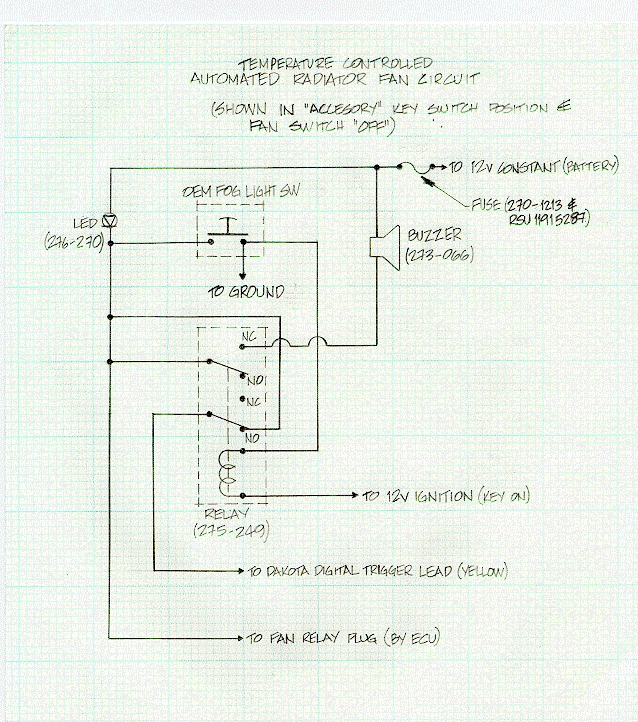
Date: Sat, 02 Jan 1999 20:00:01 -0800 I have designed a circuit that, in conjunction with a Dakota Digital
water temperature gauge, will do the following:
I scanned the sketch into a JPEG (400 KB) and have included the part
numbers (Radio Shack) of the parts I used. Alternatives can be used
where appropriate. Reply if you are interested and I will forward the
JPEG to you.
_______________
From: Carl Houseman (CHOUSEMAN@genicom.com) The factory harness sends Red/Yellow and White wires for this duty. I'm not
sure whether those colors continue after the switch connector (and too lazy
to take my car apart to see!).
Date: Sat, 22 Apr 2000 03:53:54 EDT Today I installed the PSM Variflow
fan unit.
I received the package a bit late (2 weeks) but upon receipt I was very
impressed by the quality of the unit. The control-box is no larger than a
pack of cigarettes. It has generous coils of high quality wires for the DC
power and fan outputs pre-soldered to the unit. There are numerous inputs,
one for switched +, A/C switch and the thermo-sensor. I opted for the
"temp-clip" thermo-sensor for installation simplicity sake.
I mounted the unit on top of my intercooler duct adjacent to my MSD. It
requires some cooling space around it so this placement worked out great.
Installation was almost uneventful.
I determined the "high" speed of the fans to be the green and black wires,
green being positive. I used two pairs of female spade connectors to attach
both the positive and negative leads to the fan outputs, chaining them from
one fan to the other. I also discovered at this time that the A/C input wire
actuates the fans on a 25% speed no-matter the ignition position. I will hook
this to a cockpit mounted switch in concert with the A/C clutch to allow for
"engine off"cool-down between runs.
Following the instructions I placed the temp-sensor in the lower portion of
the radiator fins not directly cooled by the fans. It didn't work. The fans
maintained a toasty 210 degrees with the pot on the lowest setting. After
some experimentation I found the optimal placement of the "temp-clip" on the
very upper FRONT right side of the radiator, by the engine-coolant input. I
had to unbolt the A/C coil in order to place the clip. Because of the shape
of the fan shrouds and to restrict airflow around the clip to ensure
consistent fan cycling I opted to use adhesive foam and rubber grommets to
hold the temp-clip in with my fastened A/C coil. It worked...
I drove around for 30 minutes in stop and go traffic with the A/C on without
the compressor wire attached to further load the cooling system. The temp
needle maintained 180 degrees +/- 5. As a final test I let the car idle in
the driveway for another 20 minutes (A/C off). The needle didn't deviate
more than a hair from 180 on my AM temp gauge. The ambient temp was 55. The
fans were almost imperceptibly silent the entire time.
The fans operate in a weird silence. The pulse-width modulation gives a very
subtle hum upon startup and slow running. It starts the fans very slowly
accelerating them to desired speed and decelerating them equally slowly.
Nice and efficient. Good for the fans and electrical loads.
Based on my initial observations I feel the Variflow is a damned good
product. It doesn't load up the electrical system nor is it noisy and
obtrusive. It did require a bit of fiddling to find the best sensor
placement but beyond that installation was straightforward. Judging by the
meager (and near-silent) fan-speed the unit was operating at during my
initial tests I would say summer running should prove more than satisfactory.
Not bad for $100. Good stuff.
Date: Wed, 19 Jun 2002 23:09:12 -0500 After recently doing the fan mod, I grew disgusted with having to wait 30
seconds after shutting the car off to flip the switch. Explaining to
everyone who rides in the in the car why you have to sit and wait 30 seconds
is more work than it is worth. I enjoy everything else about the fan mod
and highly recommend it. So, I modded the fan mod to unground the famous
wire after 30 seconds. This involves adding a delay-timer to the fan mod
circuit. I looked into building the circuit on my own and don't feel as
though it would be that difficult.
http://ourworld.compuserve.com/homepages/Bill_Bowden/page2.htm#relay_i.gif
This shows an example of what you would need. Radioshack should sell the
goods for ~$15. After some searching I found a Delay-Timer from Elk
Products (ELK-960) for $25 from
SmartHome.com
It was worth $10 for me not to have to build the timer.
This is a brief description of the installation:
*disclaimer* Do this at your own risk. As always, if you screw up your car,
it's your fault. Be careful!
Notes : I have only had this mod on my car for today, but it is working
perfectly and I don't expect any problems. There are probably better ways
do this that would avoid having to turn on the switch 2 min before you turn
the car off. I like the way the fan mod works and didn't want to screw
around with the wiring of the fan relays. The fact that the fan mod switch
works exactly as before is a plus. I don't recommend leaving the switch on
all the time (when the car is cold, highway speeds, etc).
Total cost: ~$30.
Total time: 1 hour.
______________
Date: Wed, 19 Jun 2002 22:25:39 -0700 This is only the breadboard part of the project. You need to add some
noise filtering and bypassing stuff so the first time you drive past a
500 MWatt AM station or through a thunder storm you don't get the chip
fried. You need something like a 25 volt varister(?) for voltage spikes
and a small value ceramic cap (100 pf for high frequency RF) across the
supply leads. I haven't done this stuff since 4 MHz 8 bit Z80s were the
hot thing so I may have it a touch wrong. But if you're going to put
your own electronics project in a car, you have to protect it. The
commercial electronic equipment has it designed in - and they still
sometimes die.
[Mail me]
[To Lightning home]
[To my home page][Copyright Notice]
From: "Emilio G. Littel"
Date: Mon, 22 Mar 1999 16:30:56 -0800
>There are 4 wires on the Fog Switch connector, which two are
>used to connect the ground lead and the lead to the fan
>control module? (hint: answer should consist of colors).
From: MikeFD3S@aol.com
Subject: (rx7) [3] Variflow fan mod installed.
From: Phil (johnalla@swbell.net)
	 R3   - about half way around will give you 30 seconds
	 jp1  - SEC
	 jp2  - 1-shot
	 jp3  - begin
	 jp4  - A
	 jp5  - +
	 jp6  (if you have it) - 12v duh
	 +    - Batt const
	 -    - ground
	 tgr  - I tapped into the lighter fuse right at the fuse block
	 n/o  - one side of your fan mod switch (the other side of your switch should
	        be to the 'fan mod' wire)
	 com  - ground
From: "Dana Bourgeois" (kunda1@telocity.com)