
|
Written and Copyright 1998 By Jim LaBreck.
|
||
| 1 |
 (Click for larger view)
|
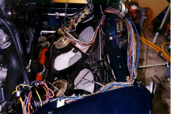
Disconnect the battery and unbolt the fuse box. The front fuse box fits nicely in a factory car, but once the intake and intercooler are replaced, it keeps the intercooler from being located more centrally in the engine bay, and blocks cold air from reaching the new intake filter. |
|
|
||
| 2 |
 (Click for larger view)
|
The wiring of the front fuse box limits the placement
possibilities for an aftermarket intercooler duct. The
ASP duct was designed to clear these wires, but in
doing so, the intercooler is placed far enough towards
the driver's side of the engine bay that it often comes
in contact with the underside of the hood. |
|
|
||
| 3 |
 (Click for larger view)
|
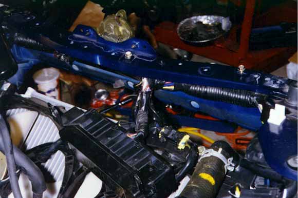
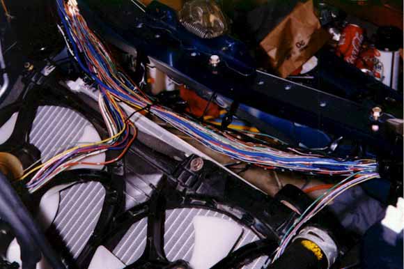
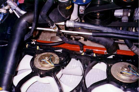
Remove the bottom of the fuse box, and expose
the wiring harness running along the underside
of the front brace. Save the plastic conduit and wire loom for re-use when buttoning up the wiring harness after the modification is completed. |
|
|
||
| 4 |
 (Click for larger view)
|
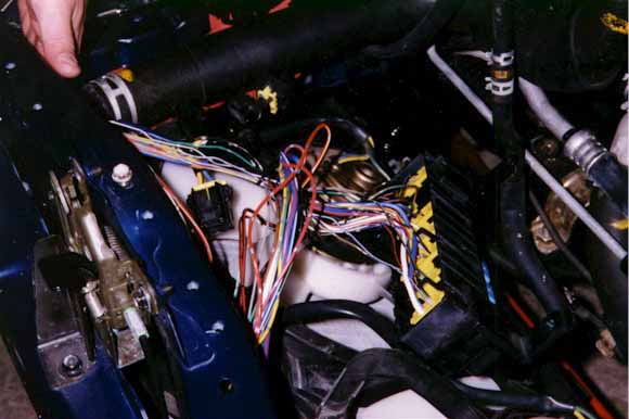
Separate the eight or so wires which run from
the fuse box to the left hand side of the engine
bay. Cut them, and group each set of ends together
with zip ties. Leave enough length on them so that
connecting the extensions won't be a problem. |
|
|
||
| 5 |
 (Click for larger view)
|
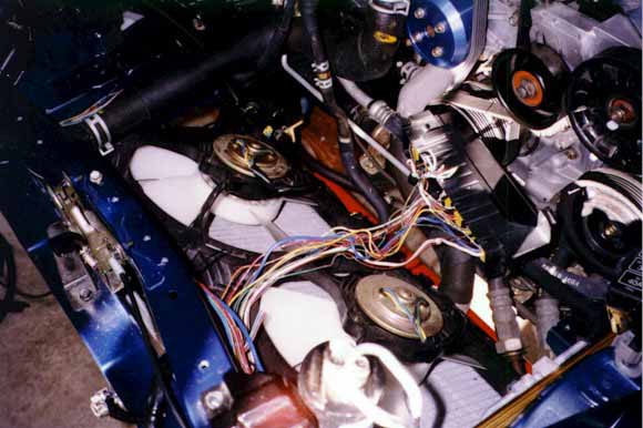
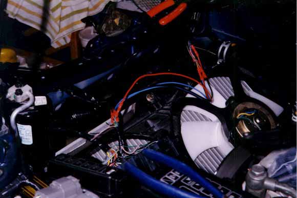
Move the fuse box to the driver's side
of the car. You can see both groups of cut wires separated and bunched together with zip ties. The large gauge wires in the foreground are the wiring for the fans. What a mess. |
|
|
||
| 6 |
 (Click for larger view)
|
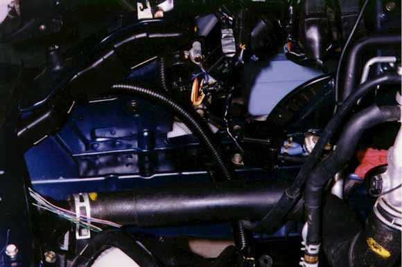
Here you can clearly see the wiring harness with
the group of wires which are still attached to
the fuse box on the left hand side of the picture
and those that were cut on the right side. |
|
|
||
| 7 |
 (Click for larger view)
|
Measuring carefully, add enough extension wire
between each of the cut wires to bridge the gap
to the driver's side of the engine bay. You can either use butt connectors or take the time to solder the connections and cover them with shrink wrap, but the results are about the same. Test each and every connection to make sure that current flows to the fuse box through the new extensions. |
|
|
||
| 8 |
 (Click for larger view)
|
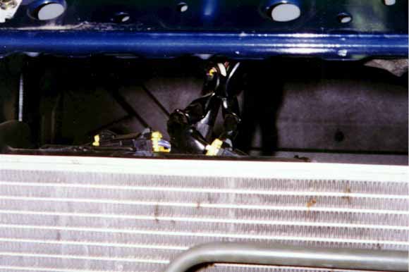
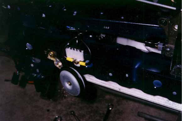
Two 10 gauge extensions will need to be added
in order to relocate the wiring for the radiator
fans. Ground them using the common grounding
point on the left hand side of the car, behind
the bumper insert. (If you happen to have the
insert and nose off the car, that is... if not,
choose another convenient grounding location.) |
|
|
||
| 9 |
 (Click for larger view)
|
Re-route the wiring for the fans along the
bottom of the fan bracket, where they will be
out of the way. You can drill holes through the bracket itself large enough to thread a zip tie through in order to hold the wiring in place. The plastic of the fan bracket is fairly soft, so you can "auger" out a rectangular hole easily. |
|
|
||
| 10 |
 (Click for larger view)
|
Route the wiring for the fan back up and
into the plastic sheath on the left hand side
of the car, and cover it with wire loom. |
|
|
||
| 11 |
 (Click for larger view)
|
Route the wiring harness, including the wires
you extended, along the front of the car, reusing
the plastic conduit that was originally on the
harness. If you used crimp connectors to install your wire extensions, then you may want to wrap them with electrical tape to protect them from moisture. |
|
|
||
| 12 |
 (Click for larger view)
|
Cut off the mounting tabs of the fuse box with a
Dremel. Cover the remaining wiring with electrical tape
and route it behind the air-conditioning cannister.
Drill two rectangular holes (front and top) just large
enough to admit a large zip tie. After wedging the bottom
of the fuse box (release tab up) into the corner of the
fan bracket, (you'll know when you've hit the right spot)
connect the fuse box to the rear line of the cannister
using a large zip tie. |
|
|
||
| 13 |
 (Click for larger view)
|
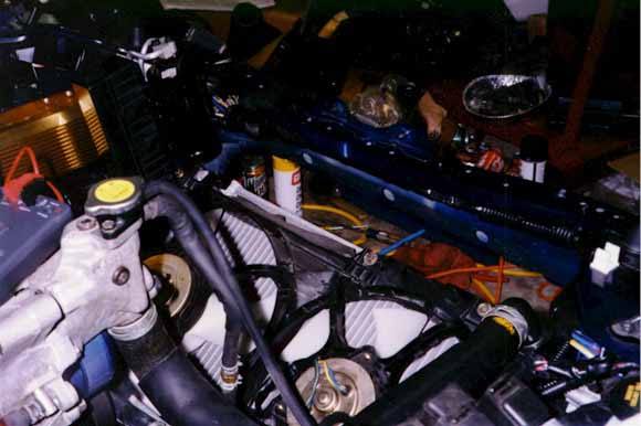
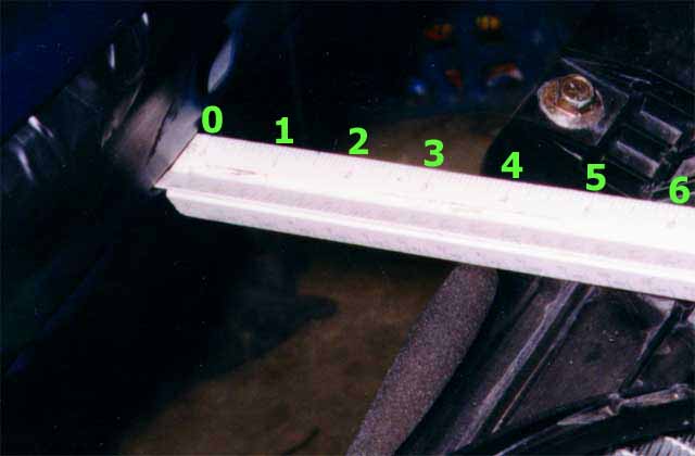
Moving the fuse box and relocating the radiator
with Trev's magic mounting blocks really opens
up the front of the car; 5 inches, all the way
across the front of the engine bay. These
modifications, along with minor cutting of the
bumper insert, allow so much air to enter the
engine compartment that my fans almost never
turn on anymore, even after hard driving. (Numbers in larger view added for reference. I rescanned the original at a higher resolution for doubters...) |
|
|
||
| 14 |
 (Click for larger view)
|
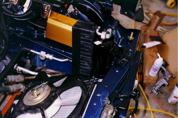
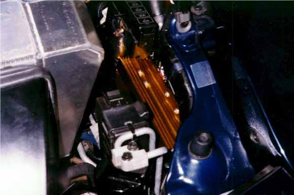
Here you can see the fuse box tucked into the corner
created by the ASP intercooler. The Crane HI-6 is
mounted immediately to its right, and you can see the
modification to the battery mounting tab where a
Streetwires gold connection is covered with clear
vinyl. |
|
|
||
| 15 |
 (Click for larger view)
|
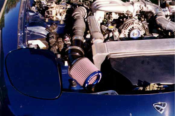
On the other side of the engine compartment, the custom
cold-air intake turns the corner after the ASP intercooler
and is directly in line to receive the benefits of the
widening of the engine bay opening. The fans rarely turn
on, which means that no plate is necessary to cover them,
because no warm air is being blown at the intake filter.
The intercooler is always extremely cold to the touch,
even on hot days. |

![[ Mail me ]](mail.gif)
![[ To Lightning home page ]](rx7_home.gif)
![[ To my home page ]](my_home.gif)
![[ Copyright Notice ]](copyright.gif)