
Push Button Start Installation Instructions
Last updated: September 2, 2002
(Editor's note: Jon wrote this for the start button from a Honda S2000
(i.e.- he got it at a Honda dealer). If you have an aftermarket one like
the Ignited button, the procedure may vary, so please check the wiring
diagrams and other instructions that come with your button. Other
differences may occur as well (e.g.- might not need to enlarge the cig.
lighter hole).
From: Thomas, Jon (Jon.Thomas@dayzim.com)
Date: 07/03/2001 04:25 PM
Parts & Tools:
- OEM S2000 button
- auto relay w/4 blades (bought mine at Radio Shack, 30 amp minimum, around $5)
- spool of 20 awg and 12 awg wire
- many wire butt connectors (various sizes, some with and
some without insulation)
- various wire taps and blade connectors
- very small shrink wrap
- mounting media (used super glue and 3M tape)
- Dremel tool to slightly enlarge cig lighter hole (necessity)
- wire tester (very helpful)
Install Time: takes appox. 4 hours for complete job
Install cost: Total - approx. $50
Assuming you have all of the parts, these are the steps you should
take to do the install.
By the way, I am not responsible for you vehicle or your installation
procedures. These are the steps that I took and if done correctly should
give you the same results.
- Disconnect negative battery terminal
- Dismantling dash - First thing to do is take off all dash parts surrounding
the steering wheel (including gauge cluster and of course the housing
surrounding the steering column). The gauges will have to be unhooked as well
as the cig lighter and the pop up headlight switch. Check the better RX-7 How
To sites if you would like help dismantling this part of the car (that is what I did).
- Prepping the button - You will need to open the switch to verify exactly which
leads go where and compare them the wiring diagram that we have provided, double
check the configuration. We cut off the plastic (used for the factory S2000 harness)
surrounding the 5 leads with the Dremel tool. We cut off the two leads that are not
used inside the button in order to allow more room to connect wires to the remaining
3 leads (which you will notice is not that much room, we actually bent them slightly
apart too). Of the remaining three leads, the middle one should be the common power
lead for the light and the button. The lead on one side will be the ground for the
light where as the other lead will be the lead for the button going to the relay
(see diagram). At this point you will want to attach your 20awg wires to all three
leads with bare/un-insulated butt connectors. We used three different colors of
wires (ex. red for power, black for ground, green for the relay), this made it
easier later on to distinguish the switch leads. Leave plenty of wire attached
to the leads just in case you need it later on. Take the shrink-wrap tubing and
place it around the connections so that the leads never touch and short out. We
then wrapped the wires in 5” of wire loom to keep them all together and easier
to work with. You can then set the button aside for later mounting.

- Prepping the mounting location – You must first remove the cig. Lighter and
all associated pieces, save and set them aside for now. The remaining hole is
too small to accommodate the button. So, we took the Dremel tool with a grinding
attachment and ground down the inner edges of the hole until it fit perfect (btw
don’t breath the burning ABS plastic fumes, they are toxic). Take off a little
at a time and keep trying to see if it fits. Remember it is better to go slow
instead of taking a bunch of material off and making the hole too big. Stop
when you are able to slide the button through the hole and notice that it fits
flush with the seat just snug (it does not need to be tight).
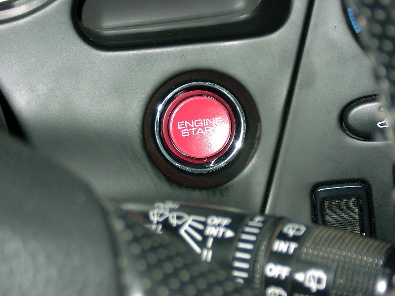
- Mounting the button – Take the button and place it in the hole. We made sure
the words are facing upwards correctly and applied a little bit of super glue
on the back of the chrome ring of the button. This helped it from not turning
inside the hole. Next we wrapped the button housing with one piece of 3M
double-sided tape and placed the original plastic cig. lighter heat shield
around the button, securing it with the two screws (the plastic housing may
only touch the button housing in a few spots). We also wrapped tape around
the back of the button and the screwed in mount from the cig lighter. This
helped to hold the back of the button. You now have the button mounted in its
new home. You can now turn the gauge cluster over to see what it is going to
look like (sweet isn’t it).
- Wiring the key switch harness - Since you have all the dash parts off, you
should be able to see the harness that is running into the key switch
assembly. The harness runs under the steering column and to the left side
of the column and then down the column from there (just follow it from the
key hole and you will find it). Detach the harness at the back of the key
switch. You will need to cut one wire from the harness and tap into another.
Cut the 12 awg starting wire on the key switch harness. It will be a black
wire with a blue stripe (see wiring diagram). Once the cut has been made,
tape off the end that is going into the key switch. Next, take a 36” long
piece of your 12 awg wire and connect it to the other end of the black and
blue wire you just severed, use a shielded butt connector. Next tap into,
DO NOT CUT, the black with green stripe wire with another 36” long piece
of 12 awg wire & wire-tap. Re-connect the factory harness into the key
switch.
- Wiring the relay –Bring in the gauge cluster with the newly mounted
switch. Select a home for the relay, we choose to 3M tape it to the back
side of the upper gauge cluster supports (but don’t stick it in place yet,
just know where you are going to put it so you can trim all the wires
accordingly). Run the wire form the start button switch to the relay using
female blade connectors, taking care to route them under supports and such.
You don’t want to crimp or pinch any of these wires when re-assembling the
dash. Use the wiring schematic for details. Now run the middle wire from
the button to something that is powered up by the “ON” position of the key
switch (WARNING do not use the “ACC” position, the starter will work but
the engine will not start). We tapped into the cruise control power lead
(which you have to test to get the right wire on the cruise harness, I
believe it was the third from the left, but double check it). The last
wire on the button goes to a common ground. The other blade on the relay
also goes to a common ground. .BTW, we tapped both grounds (button & relay)
into the Cruise Control ground. The last two 12 awg wires will need to go
up to the relay. Connect these using female blade connectors also.
- Test – Place the ground cable back on the battery and do not tighten.
Place the key in the ignition and turn to the “ON” position. Push the
start button!!! It should start right up. Turn the engine off and finish
up. If it does not start recheck all connections including the battery.
- Reassemble dash – Put the dash back together.
Note: The switch was $30 from www.handaaccessories.com or
www.handaparts.com, which are direct factory OEM parts.
We wired it so the key has to be in the run position, when in that position
the button can be pushed to start the engine. If I turn the key to start
(factory) it does nothing but spring back to the run position. The light for
the switch comes on when the key is in the accessories position.
________________
Date: Wed, 1 Nov 2000 08:31:52 +0100
From: "Bernd Kluesener" (bernd.kluesener@stt.se)
At the ignition switch:
Black/red wire:		start
Black/white wire:	run
Black wire:		supply from battery (2 cables)
Blue wire:		accessories (cig lighter, audio system  etc)
Black/yellow wire:	wiper motor, power window, sunroof, ABS
_________________
From: Thomas, Jon (Jon.Thomas@dayzim.com)
Date: 07/03/2001 03:48 PM
The relay is a definite need for this mod. We did notice that on the Mazda
wiring diagram it is pulling 40 amps. We used a 30 amp relay just b/c it was
easier to come by. If you can find a 40 amp relay I would use it. With me
living in Phoenix, AZ, i don't believe I am going to have much of a starting
problem, so it wasn't too big of a concern for me. Someone that lives
elsewhere might be a little more concerned with the amperage.
_________________
(Editor's note: I sent an email to TDSA, which is where I bought
my Ignited brand push button. Here is their rsponse. --Steve)
From: TDSA SPORTS (tdsasports@yahoo.com)
Date: 07/25/2001 12:37 PM
> I bought one of your start buttons, and had a
> question:  The install instructions say that a
> 40 amp relay is required.  But what are the specs?
> I have found a couple of kinds:  SPDT, and SPST.
>
> What kind is required?
Any 30 amp - 40 amp relay is acceptable.

[Mail me]
[To Lightning home]
[To my home page]
[Copyright Notice]