

The Complete Guide to Intercooling
Part 1 - If you run a turbo or blown car, you need an intercooler for
best performance.
By Julian Edgar
From Autospeed Online
When a turbo or supercharger compresses air, the air is heated up. While this hot air can be fed straight into the intake of the engine (and often is), there are two disadvantages in taking this approach.
Firstly, warm air has less density than cool air - this means that it weighs less. It's important to know that it's the mass of air breathed by the engine that determines power, not the volume. So if the engine is being fed warm, high pressure air, the maximum power possible is significantly lower than if it is inhaling cold, high pressure air. The second problem with an engine breathing warm air is that the likelihood of detonation is increased. Detonation is a process of unstable combustion, where the flame front does not move progressively through the combustion chamber. Instead, the air/fuel mixture explodes into action. When this occurs, damage to the pistons, rings or head can very quickly happen.
If the temperature of the air can be reduced following the turbo or supercharger, the engine will have the potential to safely develop a higher power output. Intercoolers are used to cause this temperature drop.
There are a number of factors that affect the temperature increase that occurs when the air is compressed. Firstly, the higher the boost pressure, the greater will be the temperature increase. As a rule of thumb, if you are using a boost pressure level of more than about 0.5 Bar (~ 7 psi), an intercooler is generally a worthwhile investment.
Secondly, the lower the efficiency of the compressor, the higher the outlet air temp. However, it is difficult to accurately estimate the efficiency of the compressor and even if such a figure is available, it doesn't necessarily apply to all the different airflows that the compressor is capable of producing. In other words, there will be some combinations of airflow and boost pressure where the compressor is working at peak efficiency - and other areas where it isn't. While a well-matched compressor should be at peak efficiency most of the time, in some situations it will be working at less than optimum efficiency. This will change the outlet air temperature, usually for the worse.
Thirdly, the turbo- or supercharged car engine is not working in steady-state conditions. A typical forced induction road car might be on boost for only 5 per cent of the time, and even when it is on boost, it is perhaps for only 20 seconds at a stretch. Any decent forced induction road car will be travelling at well over 160 km/h if given 20 seconds of full boost from a standstill, meaning that longer periods of high boost occur only when hill-climbing, towing or driving at maximum speed. While all of the engine systems should be designed with the maximum full load capability in mind, in reality very few cars will ever experience this. This factor means that the heat-sink ability of the intake system must be considered.
If the inlet air temperature of the engine in cruise condition is 20�C above ambient, then on a 25� day the inlet air temp will be 45�C. After 30 minutes or so of running, all of the different components of the intake system will also have stabilised at around this temperature. If the engine then comes on boost and there is a sudden rise in the temp of the air being introduced to this system, the temperature of the turbo compressor cover (or blower housing), inlet duct, throttle body, plenum chamber, and inlet runners will all increase. These components increase in temp because they are removing heat from the intake air, limiting the magnitude of the initial rise in the actual intake air temperature. As a result, the infrequent short bursts of boost used in a typical road-driven forced-induction car often produce a lower initial intake air temperature than expected. This doesn't mean that intercooling is not worthwhile - it certainly is - but that the theory of the temperature increase doesn't always match reality.
An intercooler will do two things - it will lower the temperature of the intake air and at the same time, cause a slight drop in boost pressure. The latter comes from the restriction to flow caused by the intercooler. Some restriction is unavoidable because the flow through an efficient intercooler core needs to be turbulent if a lot of the air is to come in contact with the heat exchanger surfaces. However, if the pressure drop is too high, power will suffer. A pressure drop of 1-2 psi can be considered acceptable if it is accompanied by good intercooler efficiency.
Intercooler efficiency is a measurement of how effective the intercooler is at reducing the inlet air temperature. If the intercooler reduces the temperature of the air exiting the compressor to ambient, the intercooler will be 100 per cent efficient. It will also be a bloody marvel, because no conventional intercooler can actually achieve this! Typical figures for a good intercooler are around 70 per cent.
Most intercoolers fall into two categories - air/air and air/water. There are also those special designs that cool the intake air to below ambient temperatures, using ice, the air-conditioning system or direct nitrous oxide sprays, but they will not be covered here.
Air/air intercoolers are the most common type, both in factory forced induction cars and aftermarket. They are technically simple, rugged and reliable. An air/air intercooler consists of a tube and fin radiator. The induction air passes through thin rectangular cross-section tubes that are stacked on top of the other. Often inside the tubes are fins that are designed to create turbulence and so improve heat exchange. Between the tubes are more fins, usually bent in a zig-zag formation. Invariably, air/air intercoolers are constructed from aluminium. The induction air flows through the many tubes. The air is then exposed to a very large surface area of conductive aluminium that absorbs and transfers the heat through the thickness of metal. Outside air - driven through the core by the forward motion of the car - takes this heat away, transferring it from the intake air to the atmosphere.
Described above is what is normally called the intercooler 'core' - the part of the intercooler that actually effects the heat transfer. However, there also needs to be an efficient way of carrying the intake air to each of the tiny tubes that pass through the core. End-tanks are used for this, being welded at each end of the core. While some cores are 'double-pass' (the inlet and outlet tanks are at one end separated by a divider, while at the other end the air does a U-turn), most cores are single-pass, with the inlet at one end of the core and the outlet at the other.
Good intercooler manufacturers have two specifications available - the pressure drop at a rated airflow (with the airflow often expressed as engine power), and the cooling effect (normally expressed as a temperature drop at that rated flow). However, many intercooler manufacturers have no data available on either of these factors! To some extent this doesn't matter greatly - the design of the intercooler is normally limited by factors other than heat transfer ability and pressure drop. Because an air/air intercooler uses ambient air as the cooling medium, an air/air intercooler cannot be too efficient - simply, the bigger the intercooler, the better. In fact, the maximum size of an air/air intercooler is normally dictated by the amount of space available at the front of the car and the size of your wallet, rather than any other factors!
It's easy to see how cost is a vital factor - those forced induction cars produced by major car companies as homologation specials (either for rallying or circuit racing) have quite huge intercoolers that dwarf the ones fitted by the same companies to their humdrum cars. Nissan used an air/air core no less than 60 x 30 x 6cm on their R32 Nissan Skyline GT-R and the Mitsubishi Lancer Evolution vehicles also use huge intercoolers. The "bigger is better" philosophy can be clearly seen at work in these cars.
Many factory-fitted intercoolers are undersized. Air/air cores no larger than a paperback book can be found in turbo cars with a nominal maximum output of 150kW. Cars equipped with this type of intercooler can be held at peak power for only a very short time before the increasing inlet air temperature causes the ECU to retard timing or decrease boost. A car fitted with this type of tiny factory intercooler is almost impossible to dyno test - the intake air temp rises so fast that rarely can more than one consecutive dyno run be made before the intake air temp is so high that the engine detonates... On the other hand, the aforesaid Skyline GT-R has a measured intake temp of 45?C on a 35?C day at 1 Bar boost and a sustained full-throttle 250 km/h!
When either increasing the size of a factory intercooler or installing a new one for a custom forced aspirated car, care needs to be given to the location that is chosen. The first point to consider is the amount of ambient heat that is present. An intercooler core absorbs heat just as well as it sheds it. This means that an underbonnet intercooler core can easily become an intake air pre-heater if care isn't taken with its location. Turbo cars run especially high underbonnet temps and so a bonnet vent designed for intercooler cooling while the car is under way can easily become a "chimney" ducting out hot air while the car is stationery - hot air that passes straight through the intercooler core. In fact, the behaviour of the intercooler while the vehicle is stopped is very important if you're in the habit of caning the car in traffic light Grands Prix!
By far the best location for an intercooler is in front of the engine radiator. The car manufacturer will have aerodynamically tested the vehicle to ensure that large volumes of air pass through the engine cooling radiator, and so an intercooler placed in front of that is sure to receive a great amount of cooling air. Note that the intercooler should be in front of any air conditioning condenser as well!
The air/air core should be ducted with the cold air if at all possible. Many people simply place the intercooler at the front of the car, hoping that the air being forced through the front grille will all pass through the intercooler. However, if there is an easier path for the air to take, that's the way it will go. Sheet metal guides can be used to channel the air coming in the grille through the intercooler, and foam rubber strips can be used to seal the escape routes that the air might otherwise take.
The plumbing leading to and from the intercooler should produce only a minimal pressure drop. Factory turbo cars often use intake ducts that smoothly increase in size from the diameter of the turbo compressor outlet (often only 50mm or so) to the inlet diameter of the throttle body (perhaps 80mm) and if this can be done, it's an approach which should be followed. Intercooler plumbing should have gentle curves and be as short as possible. Don't forget when you are planning the plumbing that the engine (and so also the blower or turbo!) moves around, while the body-mounted intercooler core does not. This means that some rubber or silicone hose connections must to be incorporated in the plumbing to absorb the movement.
The return duct from the intercooler should be insulated to avoid it picking up heat from within the engine bay. Lagging the pipe with fibreglass or ceramic fibre matting works effectively without being too bulky. The pipework can be finished off with a wrapping of aluminium adhesive tape of the type sometimes used to seal roofs. Also note when planning the intercooler pipework that the compressor cover of a turbo can be easily rotated to allow the outlet to come out at a different angle. This can reduce the number and tightness of the bends required.
Some people believe that if they fit a very big intercooler with large ducts, the volume of charge air within it will unduly slow throttle response. Their concern is unjustified however - throttle response problems (for example, turbo lag) are largely the result of other factors within the forced induction system, not the volume of air within it.
There are a number of ways of getting together a very good air/air intercooler. Those companies specialising in the production of intercoolers (Spearco in the US is one of the largest) have a huge variety of cores and end-tanks available. However, as an aluminium item of fairly intricate construction, they are not cheap. For a really big air/air intercooler complete with end tanks, expect to pay about as much as you would for a turbo.
An alternative in Australia are the Japanese importing wreckers. While few factory turbo cars have really large intercoolers (and even less factory supercharged cars have them!), there are at least a couple of large ones available. As mentioned previously, the Nissan Skyline GT-R and Mitsubishi Evolution model Lancers all have very good intercoolers. The Nissan Pulsar GTiR also has a large intercooler (pictured), while the Mazda RX7 single turbo Series 4 has an engine-mounted intercooler that has a good flow, despite its appearance. Welding two of the RX7 intercoolers in series has also been shown to work very well.
You can also produce your own intercooler by modifying heat exchanger cores designed for other duties. However, having personally done so, I can advise that it is a great deal of work! One source of efficient heat exchangers are old airconditioners. Domestic and industrial refrigerative airconditioners use copper tube and aluminium fin heat exchangers for both their evaporators and condensers. When the airconditioner is discarded (perhaps because of a faulty compressor) these components are sold off at scrap value - less than the price of a few spark plugs! If you are patient and handy, you can cut off each end of the core and make plates that fit over the multiple copper tubes. Making end tanks that attach to these baseplates is then straightforward. The resulting copper-cored air/air intercooler is efficient and very, very cheap.
Another alternative it is to visit truck wreckers. Diesel turbo truck intercoolers are absolutely huge. They can also often be picked up very cheaply from insurance repair jobs, where the core has been twisted slightly, or one end tank damaged perhaps. If you chose with an eye to modification, the core will be able to be shortened without new end tanks being required - which substantially reduces the amount of work! This way you need only make new blanking plates for the ends of the shortened tanks. However, be aware that reducing the number of tubes of a truck intercooler in this manner can also reduce its flow by an unacceptable amount.
________________
Autospeed Online also has an article on air/water ICs.
Date: Mon, 28 Jul 1997 23:46:09 -0700
From: elitemotorsports@juno.com
FYI, the Nuformz intercooler (front mount) is simply an APex'i, Japan IC core/kit.
GReddy/Trust IC kit: mounts to stock IC location, comes with 2 pipes/joints leading from top and bottom of IC, 4 blue silicon hoses and 8 clamps. Mates to stock plastic pipes perfectly. 3 row IC fins. Great fit and finish. More than sufficient for you circuit (road) racers out there (ditto me).
(GReddy/Trust also offers a front mount but it's only for the single turbo upgrade use.)
HKS IC: Front mount is way too $$$ expensive at over $2000.
A'Pex'i IC core/kit: Not bad, 3 row IC core, close to $2000 also.
PFS IC: nice red paint, other than that, the core is not much bigger than the stock IC. The end tanks take up more space than the IC fins/core.
ASP IC: Nice looking units (on Kevin's car), his performance proves it works. Fit/finish looks good too. Spearco core (?)
Blitz IC: WAY over prices ie all their products. Low to nil market presence (in the US, at least).
From: Rick Zehr (rzehr@pacbell.net)
Date: 03/21/2002 10:38 PM
For those who are considering one of the less extreme intercooler upgrades, here is some info won from personal experience and a lot of research on the topic.
There is an exception to the last statement, but I do not recommend it: the SR and Greddy ICs can be used with the stock airbox if you cut a hole in the bottom of the airbox and create a duct downward next to the radiator, forsaking use of the stock flat intake pipe. I tried this, and didn't like it - the intake air was hotter, much dirtier, and much wetter than that from the mouth of the car. When used along with the flat stock airpipe, it also organ-piped at various frequencies.
If you go with anything but the Blitz, plan on spending hours fabricating or
buying some ductwork to get air to the IC and fitting it, and plan on mangling
or replacing the stock plastic ductwork. The Greddy, while a very nice "stock
mount" IC, requires work on ducting air to it, or you will be forsaking the use
of one column of the IC on the driver's side, and a couple of inches across the
top.
I hope this helps save others some time. I bought one used IC and was ready to install it, until it became evident how much work it would require on other aspects of the car to accomodate the IC. I now have a Blitz stock mount (which really is), and found it to be a much greater performance improvement than a RB cat-back (long since sold), with much less noise.
_______________
Date: Fri, 20 Mar 1998 10:41:05 -0500
From: Rippin (rippin@pottsville.infi.net)
For all you fellow members looking for intercoolers out there, here are some Specs on the core sizes of each:
Intercooler		Thickness	Width		Height		Volume
________________________________________________________________________________
Stock IC		2.5 		11.5		4.5		129.375
ASP medium   		3.5		12.55		11.55		507
ASP race		3.5		12.55		17		746.7
Greddy Stock location	4.0		12.5		7.5		375
Greddy Front Mount	4.0		16.0		10.5		672
PFS			3.5		10.4		10.5		382.2
Pettit Cool charge2	3.5		10.5		10.0		367.5
__________________
Date: Tue, 10 Jun 1997 19:45:05 -0500
From: "Kevin T. Wyum" (aspi@winternet.com)
Okay, as promised I got the actual numbers and performance data for a few intercoolers. Although it was claimed that we would never know a real answer on the issue of IC's here it is. As the data shows below it is very clearly the case that a bigger IC core will increase performance. I hope this will now put the debate to an end and that the detractors will realize the error of their theories.
I'm not pushing any particular product, I'll let Brian at Mostly Mazda or Cam at Pettit do that. These happen to be examples that I have data on for obvious reasons and another example to prove the point.
These tests were done by Spearco who maanufactures the core itself for all of these intercoolers, the data is provided by Spearco. There is no potential bias involved.
Based on John Duff's reply on one of the posts I feel that I should define what pressure drop is. If you need further explanation of it just ask. Pressure drop is measuring the difference in pressure across the IC with no airflow through the outside. It tells you how restrictive a core is. If the core has a small number of passages for air to travel through it will be more restrictive. In a practical sense what it tells you is that the turbos will have to produce x * more psi than what you see at the manifold because it has to overcome the restriction at the IC. For example if a core has a pressure drop of 1 psi that means the turbos will put out 16 psi in order to see 15 at the manifold. Of course the higher the number the harder the turbos have to work and the hotter the charge temp will be on that side of the IC.
* x = pressure drop across the core.
PFS IC
Core 3.5" x 10.4" x 10.5" CID of core 382.2
CFM of air flowed at 1.5 psi of pressure drop 410
Pressure drop at 10 psi and 6000 RPM 1.25 psi
Efficiency of heat transfer at 5mph air speed through core. 43%
Efficiency of heat transfer at 20mph air speed through core. 71%
ASP Medium IC
Core 3.5" x 12.55" x 11.55" CID of core 507.3
CFM of air flowed at 1.5 psi of pressure drop 620
Pressure drop at 10 psi and 6000 RPM .6 psi
Efficiency of heat transfer at 5mph air speed through core. 56%
Efficiency of heat transfer at 20mph air speed through core. 86%
ASP Race IC
Core 3.5" x 12.55" x 17" CID of core 746.7
CFM of air flowed at 1.5 psi of pressure drop 760
Pressure drop at 10 psi and 6000 RPM .35 psi
Efficiency of heat transfer at 5mph air speed through core. 76%
Efficiency of heat transfer at 20mph air speed through core. 88%
Small core unknown what application it is used in. Example of small core
Core 3.5" x 6.6" x 11.55" CID of core 266.8
CFM of air flowed at 1.5 psi of pressure drop 320
Pressure drop at 10 psi and 6000 RPM 2.2 psi
Efficiency of heat transfer at 5mph air speed through core. 38%
Efficiency of heat transfer at 20mph air speed through core. 70%
(This is actually a dense fin design core and pretty good for its size)
So as you can clearly see by the data a bigger core will produce temps closer to ambient at all speed ranges and do so with less work on the part of the turbos. So additionaly you could expect more life out of your turbos with a less restrictive core. Please also note a large core will actually reduce the temperatures more than a small one at even 4 times slower air speeds. So the arguement that the opening over the radiator top is only so big is an invalid point.
_________________
From: kevin kelleher [SMTP:kellehkj@earthlink.net]
Sent: Friday, January 21, 2000 10:58 PM
Based on Jeff Hoskinson's recent post on the SR IC, I finished up this comparison in progress........
If you mostly putt around like a new vette owner, the stock set-up is fine. If you occasionally get on it for short blasts, the RB duct will help power.
But, if you track the car, or otherwise drive hard with sustained boost, the stock IC should be replaced with a larger unit with a dedicated air supply. Check Rob Robinette's site for more on this. At stock boost, and separated intake air, I still measured over 190F charge temp at the track with stock IC. Many trackers still use the stock unit, with minimal mods. For them, a small IC upgrade (SR) may now make sense.......
   VOL = gross core volume
   FA  = gross charge flow area (actual flow area around 40% of this, less for
         stock and Greddy tube type cores)
   CA  = gross cooling surface area
***The 'SR' W and L dimensions are approximate, could be 12 x 6.4
In general, a large FA reduces pressure drop, and cooling efficiency is mostly improved with large VOL size and 'L' dimension.
Currently available small IC's (all use stock air duct, and the M2 and SR use stock hoses.....not sure on the blitz):
 TYPE---[ W   L   T ]---VOL--[FA, CA]--$$$

 STOCK--[ 11.5" 4.5" 2.5" ]--129---[29, 52]--xxxx
 M2/MC--[ 11.5" 4.5" 3.0" ]--155---[35, 52]--$540
 BLITZ---[ 11.0" 5.5" 4.0" ]--242---[44, 61]--$950
 SRMS--[ 11.5" 6.7" 3.5" ]--269---[40, 77]--$725 ***

 Popular Mid Sizes:

 GRED--[ 12.5" 7.5" 4.0" ]--375---[50, 94]--$1200 no duct
 PFS---[ 10.4" 10.5" 3.5" ]--382---[36, 109]--$1350?


 The BIG Guy:

 M2(med)--[ 12.6" 11.5" 3.5" ]--504--[44, 145]--$1500+?
The M2 (Mazda comp?) small proved to be no better than stock on the SCC test, and above number explain why. Who knows why Brian carries it.
The Blitz is a work of art, but not a great value. With a 4 inch thick core, it should have very low pressure drop. It also may work OK with a slightly mod'd stock duct.
The SR unit is the best bang for the buck, among the smalls. It should have a little less pressure drop than the PFS. It's a nice bridge between stock and mid units. It is also the longest of the smalls, which improves the efficiency. It will require some careful surgery to the stock duct for proper cooling. But if you are tempted by the SR $300 pipe set for it, the total is less of a bargin at $1000+. Hope SR does some tests for pressure drop and charge temp, at a road course, vs the stock unit.
But a better buy would be a used mid sized unit, like Greddy, PFS, and the Pettit-2 unit, if available. To get the most from the Greddy, a Pettit (or PFS) duct must be modified for it. Those trackers at stock boost, with nearly all intake and exhaust mods(but no midpipe), should advance to a least the mid sized IC.
As always, you should check fuel mixture with any mod. Fuel will likely be an issue with the larger M2 IC's.
Vendor alert - Peter (elitemotorsports@juno.com) and Trey Cobb (trey@rx-7.com) are vendors - they seem like good guys, but I just wanted to make sure when people know the info is from a vendor. --Steve
Date: Thu, 23 Oct 1997 23:42:04 -0700
From: elitemotorsports@juno.com
A news flash: GReddy has come out with their FRONT MOUNT IC kit version for the FD3S (3rd gen RX-7). We received word about this earlier in the week and the specs on the intercooler are: 400mm x 265mm x 85mm. List price on this kit is $1580, but we offer a better price for fellow FD owners. Please visit our web page to find out more.
__________________
Date: Mon, 10 Nov 1997 14:50:21 -0800 > very interested to test the two to see how they compare. Anyone As far as sizes go, the GReddy Front Mounted IC is 16" long, 10.5" Tall,
and 4" thick (not including end tanks).
I have some pictures of one installed on a '94 Touring but he supposedly
got an early kit and the other shop modified some of the piping to make it
work with the stock turbos. The kits come in two different piping
configurations, stock twin turbos or GReddy single turbo. The core and
brackets are the same.
As far as overheating, it's the same song and dance. The radiator is
tilted up a little for more direct air flow (even though it's through the
IC) but even in the stock configuration, the radiator relies heavily on the
fans for air flow. Air flow through the IC should also be decent since it
doesn't use a typical Spearco square tube core. The GReddy uses a round
tube core design with better inner fins for more cooling and flow.
The IC does sit right up in the front of the stock air dam so rock
punctures are possible. You might want to install some racing wire mesh
before the IC to keep rocks, small animals and children out. ;-)
I'll try and put pics of the new IC installed up on the
web site tonight.
Right now we have the kits for the single turbo in stock and we are taking
orders for the stock turbo kits. (Unfortunately there is a waiting list
for the stock turbo kits). This kit will take a few hours to install and
if you want a unit immediately, you can use the single turbo kit and just
modify some pipes.
The list price on the unit is $1580, complete for either stock turbos or
GReddy single turbo.
________________
The following note from Brooks refers to the older Greddy IC. --Steve
Date: Tue, 29 Jul 97 09:09:07 -0500 I have seen the Greddy Kits. The one I saw didn't even come with a duct
to route the air to the IC! What a waste with the IC just sitting there.
Also be warned the Greddy is pretty small and looks no bigger than the
PFS unit.
_________________
Date: Sat, 4 Apr 1998 23:10:22 -0800 I had to trim my stock duct and fab some aluminum extensions to fully utilize
the Greddy intercooler. It was quite easy.
_________________
Date: Sun, 5 Apr 1998 18:07:00 -0500 Even with this mismatch, the Greddy is still a lot better than stock! It's
over twice as big as the stock one.
Kevin Wyum, owner of ASP, has sold the rights to manufacture the ASP IC to
Mostly Mazda. --Steve
_______________
Date: Thu, 26 Nov 1998 04:38:21 -0500 Based on what I have heard, read, seen, etc...
The ASP ICs are perhaps the best ICs you can get. You have to get the
GReddy piping kit elbow (I think Pettit and ASP might be making their
own soon -- so check with them first), but the IC kit comes with the
rest of the pipes. The result is hard pipes from the y-pipe to the
throttle body that yield a short, reliable, free-flowing system. ASP is
also known for including the best ducts in their kits. The ICs
themselves have been carefully selected to give the best combination of
pressure drop and thermal efficiency. Silicone pipe connector hoses and
constant-torque clamps round out the package.
You can get the Medium IC and avoid having to move the battery or remove
the air pump. Both kits require an aftermarket intake system (available
from N-Tech, Pettit, Mostly Mazda, etc.), however.
The Race or Large IC may not require that the battery be moved, as a
soon-to-be-available small battery kit (from N-Tech --
http://home.att.net/~racin/) will yield the proper clearance.
Alternatively, a battery relocation kit is available from Pettit Racing
(http://www.pettitracing.com/). It is rumored that you can also keep
your air pump with the Race IC with a small modification (bend) to the
pipe that feeds the IC inlet. The Race IC offers maximum performance,
and the small battery kit makes it convenient -- UNBEATABLE!
Last I checked, the Race and Medium ICs were the same price -- $1500.
Plus the required piping elbow, add about $200 (really, it is a little
less). The small battery kit should be about $175 (I think?), if you
want the Race IC and want to keep the battery up front. For the sake of
cost comparison, you would need an IC ($1200-$1400) and piping kit
($300-$400) for a total of $1500-$1800, and that still does not replace
all the pipes, nor will the system be as efficient. The ASP comes in at
about the same price, but offers better performance.
ASP ICs are available from Mostly Mazda or from ASP directly.
I ordered the ASP Medium IC after doing a lot of comparisons (and before
I knew about the small battery kit!), and I really think that ASP offers
the best solution. I am not affiliated with ASP in any way, I am just
relaying the information I uncovered when I was shopping, and ASP came
out head and shoulders above the competition. As always, YMMV.
I should mention that I did not look too closely at front-mount IC kits
because their drawbacks (installation difficulty, IC core vulnerability,
impact on radiator cooling efficiency, increased plumbing volume, cost)
did not seem to outweigh their advantages (more space for a big core,
direct airflow).
______________
The Greddy elbow is the one most people are using. You do not need the
injector bosses on it, unless you are going to add extra injectors at some
point. However, most people do not add these - they put bigger injectors
in the stock locations (secondaries in the primary location is an easy
swap). --Steve
______________
Dana responds regarding how to keep the airpump with the ASP Race IC. --Steve
From: Dana Bourgeois MM had a custom bent intake pipe made for me out of the stock straight pipe.
I'd bet that M2 will start supplying either pipe as required although the
bent one may cost more. If not, start asking Brian and Mark about it.
Making the bent pipe is pretty easy compared to making some of the other
parts M2 sells. It could just be a case of enough demand.
_______________
Date: Mon, 28 Jul 1997 23:16:24 -0500 (CDT) I love the ASP medium sized IC, but it DOES NOT replace the stock IC
perfectly. You need a different intake system and it will fit
perfectly...no hood rubbing whatsoever. I would not consider buying an IC
that works with the stock intake as it surely would be too small and not
worth the expenditure. The medium ASP IC will, however, fit with the
battery and air pump underhood. If you use the big air duct supplied your
charge temp will be drastically reduced. I cant believe how cool the right
side of that IC is....even on hot days. When I only had the upper duct
installed it wasn't nearly as cool. If I had to do it again I would get
the same one. I can't really say that about all my other mods so that ought
to tell you how happy I am with Kevin's unit.
________________
Date: Mon, 29 Sep 1997 02:20:50 -0500 2 or 3x the size of the stock intercooler. ASP offers two: medium and
large. 95% perfect design for the large, and 100% perfect design for medium.
The 5% fault in the large size is that the custom made air duct covers
about 98% of the intercooler, leaving a little tiny gap at the end of the
intercooler. but if you consider the size of the intercooler, it really
doesn't make that much of a difference.
Review on Large intercooler (only cos I have one!!):
Requires a bit of work. Battery location required, must be used with an
aftermarket intake. won't fit w/stock airbox. Cool to the touch after hard
runs!! which is actually pretty amazing!! Fan can be turned on to draw
additional cool air to the intercooler anytime.
______________
Date: Tue, 4 Nov 1997 16:09:04 -0600 Actually Brian at Mostly Mazda stumbled on this, not me since I don't do
many of the medium IC's in person.
I've posted about the medium one before as far as performance specs which
it outperforms any of the others on the market except the big one, not sure
about the front mount though. The core cubic dim. Is about 525 CID as
opposed to the large of 760 and stock of about 180. If anyone has that post
please put it up. Anyway the scoop is that the medium IC not only fits with
the Battery in the stock location but also will fit with the Air Pump in
place with no problem. It also fits with all but one after market intake
system and stock. In the past I have misstated that I didn't think it would
fit with the air pump either, but I was wrong it does.
That's all. Just thought people might want to know.
____________________
Someone mentioned that they thought they could have a custom mount IC fabricated
for way less than what ASP is charging. Here is Kevin's rebuttal. Lots of good
info on how the ASP ICs are designed and constructed. --Steve
Date: Tue, 13 Jan 1998 04:22:56 -0600 PRICE:
I'm glad you have dealt with Spearco. They are good people and do very nice
work. Feel free to look up a core of the same size. Also note the ASP IC
uses 2 3/4 inch output and input tubes. Why do I mention this? None of the
cheaper cast aluminum endtanks are large enough to fit more than a 2 1/2
inch tube so I have to have hand made ones. This means that the end tanks
are hand cut aluminum and then individually tig welded together. I'm
guessing you are probably using a much smaller core. The taller the core the
more expensive. 17 wide and 13 high.
The core and endtanks at wholesale, which I pay after building X many of
them cost me more than you claim the whole thing will cost. This is of
course assuming you manage to build and design your IC perfectly on the
first attempt. Not very realistic.
"Throw in a few tubes" My guess is that you also just ordered off the shelf
bends for your tubing. Sorry but I have to have the bends custom done.
Nobody carries bends in 2 3/4 to begin with and they certainly don't carry
the tight radius stuff. Call your local mandrel bender and ask him how much
to bend one 2 3/4 inch tube on the same radius. Most will not have a radius
dye that tight. Next you have to make a jig and cut all the tubes right.
Hope you do it right the first time again. Then you have to debur
everything, tig weld it all together and hopefully you just happen to have a
bead forming tool to make the hose bead. I guess if you wanted a backwater
job you could glob drops of weld on the end so the hoses don't blow out.
Now spend a couple hours polishing the tubes so everything looks nice as
well.
Okay, you're done with the metal work portion of it. Now lets do the
fiberglass duct.
Go to your local fiberglass shop, with your car and the finished intercooler
and try to describe what you want done. It has to fit very tightly into the
nose of the car and be a part that can be removed. Tell him also that it
needs to be designed with a 1/2 inch gap between the end of the duct and
intercooler itself because you will be using a commercial grade rubber trim
to seal the duct to the intercooler so that only air from the nose of the
car passes through it. Also make sure he uses high temp resin because this
will get hot. Because of the shape of everything he will tell you it needs
to be a two or three piece mold, extra cost. To top everything off ask for a
black gel coat to make it pretty. Have fun finding the rubber seal material
used. You will also have to order it in bulk.
So after a week or two of leaving your car at the fiberglass place he has
finished everything up. Let's pray he understood what you were asking for
and executed it right.
Now all that is left before you can use your intercooler is for appearance
only to have some custom silicone hose made, regular orange stuff with a
black casing affixed to it. This will also have to be a bulk order. Then
order the breeze constant torque clamps and a fan and your ready to go.
Again let's just hope you did it right the first time and didn't make a
single mistake. Trust me I did a lot of this stuff 5 to 10 times before
getting it just right.
To conclude the price issue: It's ignorant for you to suggest that a one
person effort to make a single copy could do so for anything even close to
one thousand dollars. This of course assumes that your time has no value at
all. Yes I do make a couple hundred dollars off of these but I'm not a
charity and do not claim to be. The simple fact is that if you were a
skilled metal worker and fiberglass fabricator you could probably make
everything for about $200 less. Most people are not and that's the point.
The economy of scale and skilled labor make it unrealistic for each person
to build everything themselves. The RX7 certainly did not cost Mazda $30,000
each to build. Now lets see you do it for less. You certainly have a right
to say what you believe and I respect that you had enough enthusiasm to
build something that you like. The only unfortunate thing is that as a
business I have to amoratize all of the tooling and other costs over a
smaller number of projected units becasue the 3rd gen RX7 market is so
small. If this were for a mustang, eclipse or camaro I could probably do
each one for a good deal less, but it's not so that's that.
PERFORMANCE:
This is where you really went off the deep end. Something to bear in mind
before you spout about how the ASP IC hasn't "a hope in hell" is that cars
equiped with them are a LOT quicker and faster than yours with the "far
superior front mount." You should have some data to backup your claim before
going into a public forum where the ownes of these faster cars are. Even
your 114 MPH isn't very impressive. With nothing other than a precat back
crush bent exhaust, everything else bone stock, incuding tires I ran 12.67 @
111MPH. Also remember using that horrible IC and unfortunately a PFS
computer I ran 126MPH as a best trap speed with a stock block. That's 12MPH
more than your front mount. Brooks is in the 120's now and I know a lot of
others in the 116 to 119 range. BTW radials don't change much in the way of
MPH so don't think that is the difference.
You must not be aware of this, but the duct which delivers air from the nose
of the car is sealed to IC by a rubber seal. The air passing through the IC
can only come from ambient air. Something else you are probably not aware of
is that I have temperature probes in the input tube of the IC and the output
side. I know what the temp drop is. At speed under WOT the output temp is
normally about 4 to 8 degrees above ambient. The input is often over 200F+.
I'm sure that those using the large IC can verify to a basic level that
after a full pass the output side of the IC feels like cold metal that has
been left outside overnight. Put some temp probes in your IC and tell us
what you find out, my guess is that your numbers will either be higher or
the same, not better as you assume. The purpose of the fan on my IC is to
avoid the problem you refer to. Heatsoak from the radiator while at a stop
It does a rather nice job I must say. The output temp at a rest stays a few
degrees above ambient.
Pressure drop: Unless your IC is 13" tall it will cause more pressure drop.
Hopefully we all know what pressure drop is. Generally it means that the
higher the pressure drop the harder your turbos will have to work to produce
the same amount of boost at the manifold. Temps go up from the turbo as it's
efficiency drops at the higher output pressures required because of a higher
pressure drop in the shorter intercooler. You could also think of it as a
hole in your intercooler bleeding that amount of boost to atmosphere. i
don't know which core you used so I couldn't look up the exact numbers. As
an example I'll use the PFS core, which I have done before. The PFS core is
only 2.5 inches shorter at about 10.5 " in height. With only that minimal
difference it has a whopping 3 times the pressure drop of the race IC. It
loses over a full pound of boost more than the race IC simply due to
pressure drop. My guess is that you used even a shorter core than that so it
would fit without removing the bumper. That means that you would have even
more pressure drop. A 7" core if memory serves me correctly has a pressure
drop of about 3.5 to 4 psi at the boost numbers we are talking about. That
means your front mount will require the turbos to put out 3 or 3.5 psi more
boost just to overcome the restriction of your core and reach the same
pressure at the manifold. I won't even go into the issues of losses through
all of the additional bends and new restrictions from the extended plumbing
to reach a front mount. I hope you didn't use 2 1/2 " tubes on your IC
either. If so it's the smallest point in your airstream and an additional
restriction above and beyond just the core.
It appears that you have assumed a few too many things here. I really would
like to know which core you used so I could use numbers specific to your IC
but again the PFS IC. You assumed your getting more airflow through your IC
and that was supposed to be the thing that made it superior, correct? The
PFS core at 10.5 x 10.4 x 3.5 is less efficient in lowering temperature at
20 mph of airflow through the core than my race IC is at 5 mph of airflow
through the core. I uncharacteristicly apologize to PFS for using their IC
to compare but I don't know which one Fritz is using and I'm guessing on a
cubic scale Fritz's is no larger or smaller than the PFS core. I'm not
trying to hammer on PFS here. So Fritz that means assuming your core is the
same cubic size as the PFS core you can have over 400% more airflow through
the front mount and it will still not lower the temperature as much as my
race IC. My guess is that you do not have 400% more airflow, call me silly.
We have also not talked about your front mount IC preheating the air going
into the radiator, a big no no since under race conditions the stock
radiator is about at its limit. My guess is under very hard driving you
could possibly cause the car to overheat, which as others on the list have
experienced could cost you a new motor. The other thing to think about is
that you will have to pull your ic out every so often and submerge it in
water to see if there are any punctures in the core from all the road debris
that will hit it as well as constantly straightening the fins in the IC.
So to conclude this whole thing I think you either assumed way too much or
the guys at XS are not thinking things through very thoroughly and giving
you false ideas. To be honest your front mount in all likely hood will not
lower temperature as much, will suffer from damage caused by road debris and
will create more pressure drop, which will raise the input temp and cause
the turbos to work harder, causing more backpressure in the turbine side at
the same manifold boost pressure and actually shorten the life of the
turbos, having to run on average 2 to 4 psi more just to reach the same
pressure. While our turbos are producing 10.35 psi to reach stock boost,
yours are making 13 to 14 psi to reach stock boost.
It's admirable that you had enough ingenuity to make your own but the fact
is that your cheaper IC is just that, cheaper. It will not perform as well
and will have significant drawbacks inherrant to it's design that the ASP IC
will not suffer from. Let me know when you hit 126 mph in the 1/4 with your
front mount IC and stock motor. I did with the ASP race IC and a stock
motor.
Kevin's response to another note:
>Other major bummer on the ASP IC is the height, as in most cases it will The top rubbing can be solved by a slight tap with a ball peen hammer on the
hood webbing. If people want it the core can be shortened by one ambient
row, which would eliminate this issue all together. It would lower the
efficiency a small amount, choice is up to the consumer at this point. As
mentioned below I have never seen problem with anyone having any rubbing on
the bottom of the IC if they use the flathead screws and velcro. Trev
remember the IC needs to be able to move since the engine will torque, can't
hard mount it to the body.
_________________
Date: Sun, 12 Apr 1998 21:56:51 -0400 >Reading the recent discussion on intercoolers, I'm curious ; what are the Funny you should ask; I was just reviewing some data from a couple of tonight's
runs:
At a constant 80 mph: 66-68 F ________________
Date: Mon, 03 May 1999 20:57:14 -0500 Thought I would make this formal since it was only mentioned briefly at
the bottom of a previous post on a different topic.
About a month ago Mostly Mazda (M2 Performance) took over the production
and sales of both the ASP Race Intercooler and the ASP Medium
Intercooler. The reasons were plentiful. I really didn't have the time
nor the desire to produce and support the product as it should be. I
don't think there is really any question that respectively each
intercooler is the best available for the category, (with or without
battery). Really a no brainer now that Mostly Mazda / M2 is producing
them both with an optional pipe to accommodate the air pump. Anyway, I
didn't feel it was good to have the best product and at the same time
have close to the worst service with long production times etc. Part of
the arrangement was that Mostly Mazda / M2 would keep these items as an
in-stock item and maintain the same or better quality to resolve the
only real downside, the time delays I previously had. So the following
is a rundown of what, where, when and how.
To begin with the ASP Intercoolers, (as designed by me) are only
available from Mostly Mazda / M2 Performance now. If it's coming from
another source, it's a copy and we all know how well copies normally
turn out in workmanship and reliability. Just ask the guy next to you on
the driving range who bought his King Cobra II Graphite hump shafts for
half price while in South East Asia. Sorry, you can't build quality
racing components in a dorm room. Hehehe, somebody posted about an
intake that had plastic tubing which melted after being used. Ouch.
Both ASP Race and Medium Intercoolers are now available with an optional
charge side pipe that allows the use of either Intercooler with the Air
Pump still in place and functional.
Both kits are in stock and available for immediate shipping from here on
out. If not shipped within 3 days Mostly Mazda / M2 credits $100 per
kit.
The price for a kit is actually fractionally lower now, $1495 in normal
configuration, a $50 additional charge for the new charge side tubing
for a total of $1,545 with the air pump intact.
Mostly Mazda / M2 also now sells the air pump accommodating pipe
separately to individuals who already have one of the Intercoolers for
$140.00, this allows any of the previous ASP Intercoolers to fit with
the air pump still on the car.
Here's a new twist, they are available during normal business hours. :
Contact, Ordering and support at:
M2 Performance 925-686-9047
________________
Date: Sun, 08 Aug 1999 12:07:33 -0500 I have some good intake temp readings that may interest you. SCC's Project RX-7, with
the stock-mount ASP/M2 medium IC, on a 85-90 deg F day, running the high speed east
loop of Thunderhill, with 305-310rwhp, in RACE condition (20 minutes of sustained
I-think-I'm-going-to-puke hot lapping with Brian @ MM at the wheel), I never saw intake
temps go above 150 deg. F. With the stock intercooler, intake temps were nearly 100
deg. hotter by the end of the long 125mph straight (and almost every where else as
well).
Also, with the IC upgrade, the air cooled down to a near-ambient 100-105 deg. F almost
immediatly (in the turns) during the time you lift off the gas and get on it again. In
other words, there is almost no heat soak effect that causes temps to rise and rise
over the course of time. Very consistent and very repeatable. The stock IC, on the
other hand, would work marginally for the first lap (with intake readings of approx.
225 deg. F) By the next lap, intake temps at that same spot on the track would be 250
deg. F.! The stock IC'd car (which also had a stock radiator), would begin to overheat
after 2-3 hard laps. The Project car (with radiator and IC upgrade), despite prolonged
lap after lap after lap thrashing, never crept above 210 deg. F. In fact, even while
sitting in the paddock, coolant temps were already at 210 deg. F. The 20 minutes of
hard driving didn't even phase it.
Try that with a radiator-obsuring, front-mounted IC :)
FWIW, a stock-mounted IC gets fresh air ducted to it from the front of the nose (not
underhood heat). With a large enough core surface area, you don't need a lot of air
flow for it to operate at peak efficiency. Also, with less (and more direct) intake
plumbing, it *should* have less pressure drop than a front-mounted IC system.
IMHO, if you drive your car makes good hp, and you drive it moderately hard in hot
weather, a front-mounted IC is not the way to go. This is probably why the R34 Nissan
Skyline we tested a little while ago began to overheat after just a few hard laps. No
harm done though. Unfortunately, the water seals in our rotary engines aren't so
tolerant.
_________________
Max Cooper has a nice page
on the M2 (ASP) Medium IC, with pictures, details, etc.
_________________
Date: Tue, 01 Feb 2000 22:27:19 -0500 FWIW, I just A/B tested the M2 Medium and new M2 Large ICs. The new
Large IC has the same dimensions as the old Large IC. However, the core
design is different. Whereas the old core had fewer air channels and
wider external turbulator rows, the new core is identical to that of the
M2 Medium IC... just longer. Here are the results...
Crooked Willow has
announced their new intercooler. This
mounts more or less in the stock location and is compatible with most after-market
intakes, but it does require battery relocation or miniaturization.
Includes polished aluminum pipes, carbon fiber or aluminum inlet duct, silicone
pipe couplings, high-quality hose clamps, mounting brackets and hardware. Elbow
not included (available on request, $125).
Email Duane Krumweide or
phone 858.775.4292.
Polished and unpolished shown:
From: Steven N. Burkett:
Danger. Danger. ;-)
The SR stock mount IC is NOT bolt in. Not even close.
Question: Anyone installed this sucessfully? Tips?
Comments:
The core *is* a lot bigger then the stock IC. And it more or less fits in
the space where the stocker is located. But:
Grrr....
One of the main reasons I chose this IC was stock mountability. Oh well.
Looks like what I expected would be a one hour job is leading to a
"fabricate an entirely custom ducting and intake system."
______________
Shane also has an horizontal mount IC. The possible issue with this is
that you would also need to get a vented hood that had the vents in the
right place so that air would flow through it.
Date: Mon, 23 Mar 1998 21:34:20 -0600 I just finished installing the ASP large intercooler so my medium sized
Pettit Intercooler is for sale. It has been in use for one year.
Also, the black fiberglass air ducting from the nose is a piece of crap
and did not fit any where close to air tight. I tried to fix this by
sealing it with black silicone. Well the air seal worked but I also
made a mess of the intercooler in the process and the intercooler(and
ducting) will take some time in cleaning up.
Opinions about intercoolers: If I were buying a new medium sized
intercooler, I would not buy Pettit's. The intercooler itself is fine
but it is the fiberglass ducting that really sucks. IT DOESNT FIT.
Spaces between the intercooler and the ducting is not good. I've seen
this also with Peter Farrel's intercoolers. Pettit needs to talk to
Kevin Wyum about making quality ducting. The ASP ducting fits and
seals all the way aroung the intercooler. If I were buying new and I
didnt want to worry about moving the battery, I would buy the ASP medium (assuming
the ducting is the same quality). Sure, there may be a little wait, but
that's what I would do. Unless, you are very good at making things fit
smoothly and cleanly by fabricating your own little modifications. I
would recommend all Pettit and Peter Farrell intercooler owners to buy
whatever Kevin uses to seal his ducts and use it.
Anyway, this intercooler new costs $1300.00(for that much, you shouldn't
need to make the duct air tight). I am selling the intercooler, the
ducting,two blue hose connectors, and two hose clamps.
Date: Tue, 25 Apr 2000 17:44:11 PDT The West Penn RX-7 Club had its first sporadic dyno day last Saturday. You
can check www.rx-7.org/events/dynoday2000.htm for pix, and hopefully graphs
as soon as the download process is completed.
Here are a few results/finding for comparison:
IC Upgrade:
I took 2 runs to establish a baseline, and then replaced my stock IC with a
PFS unit (about two hours between runs - 2:00-4:00, so conditions were near
identical). All other settings (manual boost valve) remained the same. The
dyno had a fairly sizeable fan, the output of which was nearly identical to
the size/shape of the IC ducting, and placed right up to the duct. I would
estimate it simulated the flow at 40-50 mph.
Other mods: N-tech intake, 3" SS dp, PFS cat-back, Pettit ECU upgrade (see
next post), Unorthodox main underdrive pulley, 11lb flywheel:
(Yes, I know the boost gauge isn't accurate to 0.1 lbs, but they are my best
estimates from the passenger seat and the relative difference should be
within .1-.2)
So, the PFS has about .4psi less pressure drop than stock, and is good for
about 15 hp/17 ft-lbs.
________________
Date: Wed, 19 Apr 2000 11:03:24 -0700 I own the PFS red, I would never buy one again. It works, but the top in top out
design makes it a PITA to work on the front of the engine, or even fit an after
market AST. The duct is okay, but if you run anything other than their intake you
have to block off the hole. Don't get me wrong, I like their products, I would
just not go with their IC again.
From: petel@electroimpact.com (pete lombrozo) I talked to randy at Mazda comp today about their new IC. It fits
the stock location (no mods) has all the correct brackets and nuts to
fit the stock hardware ducting, and costs $372.60 !
It is made by Fluidyne, is all aluminum, and is more efficient than
stock.
They have no info on performance yet, so if you buy one you have to
fill us all in on "percieved" improvement.
______________________
Date: Wed, 30 Jul 1997 13:27:18 -0800 I have seen the Mazda Comp unit at Mostly Mazda.
It is about the size of a stock IC but constructed better.
It has the same number of rows and fins.
The price is right, but the benefits are not justified IMHO.
Date: Sat, 22 Jan 2000 21:28:10 -0800 The fit to the factory duct is excellent without modifications. Actually, a
strip of 1/4 inch thick rubber weather striping around the side edges provides a
nice seal. Also, the IC comes with the necessary silicon rubber hoses to attach
to the stock piping. It takes very well to being installed with the stock air
box with only one minor modification to it the air box itself: a 1/4 inch
triangular trim to the inboard, rear mounting tab.
You are right to say it is not the best value. However, one pays extra for
looks, finish quality and style (in a "snooty & ricey" sort of way) ...=8^]
It is a very nice unit nonetheless and it fits my particular application well:
stock looking engine bay with fresh air supply to the stock airbox from the nose
of the car, and a "stealthy", boost actuated, IC water spray system.
The RX-7 Fashion IC is a front mount IC based on an Apex'i core.
Chuck gets a bit defensive here, but there is some good info on his IC. --Steve
Date: Thu, 2 Jul 1998 20:20:14 EDT I never advertised this IC kit on the list but since someone brought it and
and some people were discussing about it, I guess I am forced to jump in.
First, about the price. Not everyone thinks that Greddy Elbow is a necessrity.
It's more for the looks and only if you want to put two additional injectors
but most people won't find that necessary. That's why I include it as an
"OPTION" and it is. The IC will fit on the car without that elbow. There is
no hidden cost there. About the blue silicone hose, it's an "OPTION" too.
The kit comes with regular 3 plied orange silicon hose. If you want to look
cool and get the better silicon hoses, it's up to you. There is no hidden cost
there.
About pressure drop, Adam Saruwatari is using the Apex core and run 9
sec. How come he is not using an ASP one? I am wondering. Dont tell me he is
not trying to squeeze the most out of his car. If the Apex core has so much
pressure drop, why is he using it?
The Apex C1 core Adam is using is 5.3 inch
thick which might cause overheating on the street but in fact I choose the
Apex C2 core which is 3.5 inch thick to correct that problem.
________________
Date: Thu, 2 Jul 1998 20:35:27 EDT First, I'd like to commend these guys for making a good looking IC for
what appears to be a great price.
Second, if you look around at Steve
Cirian's site (Wyum's comment on ICs) and several other sources, you would
see that their IC is not quite optimal. You want the core cross section to
be as large as possible but, as the Fashion site says, as thin as
possible. Hence, you want it tall. Fashion make up for it by making the
core REALLY long. So, I guess what I'm trying to say is that the Fashion
appears to be a great (best maybe?) value for the non-racer. If you are a
racer and need that every bit of efficiency, it may not be the best
choice.
Disclaimer: I am not going to try and build a better mouse trap for a
lower cost. If you want a huge IC, call Spearco, they have some big ones
with the endtanks already on. Or make a set yourself. That having been
said, my site has some pics of endtanks that I designed on AutoCAD. If
they aren't too expensive, I'm going to have a set made up for myself. If
you want one, I'll just tell the CNCer to fab another set and send it to
you at cost. No duct, no core, no tubing, just two tanks. You find a
welder and do all the work.
If you want to discuss the merits of my endtanks (they were NOT designed
with a computaional fluid dynamics program like SURFCAM, PowerFLOW, etc.
which would cost you over $10,000 for the IC), feel free to email me.
Date: Fri, 26 Jan 2001 19:37:41 -0800 13" tall and 2" thick does not give a lot of internal flow area. That means
it will most likely have a lot of pressure drop, which is bad. So bad is
pressure drop that trubo expert Corky Bell says that pressure drop is the
most important factor in choosing an intercooler.
Here are the internal flow areas of some intercoolers for comparison:
Now, this number is not the only thing that determines pressure drop, as the
construction of the IC core plays a major role. And while pressure drop is
really, really important, that doesn't necessarily mean that the best choice
is the one with the lowest drop. For example, few would argue that the
GReddy stock mount IC is the best intercooler available, because it is
significantly smaller than some others and thus probably does not do as good
a job at cooling.
That said, I do think it is safe to assume that the Denso core you are
considering is not a good choice if performance is your goal. It does not
even have the flow area of the stock IC.
Date: Thu, 12 Mar 1998 06:38:36 PST I would assume the fans fit on the bottom of the radiator to continue
using the pull-through type. The warm air would bathe the bottom of the
engine, no? I don't think that it matters that the radiator is on the
bottom air-flow-wise. The volume of air that enters the mouth of the V
is pressurized by the movement of the car and held in by the sheetmetal
sides. Once it enters the mouth of the V it either goes through the
intercooler or the radiator. The distribution is dependent on the
relative resistance of one to the other.
My big question is that of intercooler heat soak from the hot radiator
below, especially at low speeds or in traffic conditions.
I know that Cam tried this configuration in the race car a while back...
even included a splitter in the middle. He determined that straight up
was better...
If I/C heat soak is not a problem, and since Kevin is working on an I/C
that's tipped forward... could fitting an ASP mondo intercooler into a
configuration like this work? ...especially with the exit ducting? No
intake duct required!
From: Stephen J Lee > Do you have the part numbers from Spearco handy? Or would they just know The part # is: 2-180
They remembered the ASP core because Mr. Spears mentioned that he didn't
like cutting off only on ambient row for Kevin.
As far as the price is concerned, I got a 20% student discount. The core
price for the above is $432 and I think they charge $20 for cutting off an
ambient and charge row off and welding a plate. So you're looking at $452
without shipping.
I almost did this myself but I caught up in some other stuff. I talked to
Incon about the silicon tubing so I would recommend them. They advertise
in "Racecar Engineering" if that means anything to you, it does to me.
They're number is 440-234-2450 and they are in Cleveland, Ohio.
________________
Date: Fri, 5 Jun 1998 02:21:24 -0700 I think I can share my experience with any of you who are interested in
making your own intercooler. I made mine in '96, therefore the parts
number described following is from my 1995-1996 Spearco Catalogue.
Please double check with Spearco, 818-901-7851, in case they changed the
part number.
The core I adapted has part# 2-192 and the size of the core is 3.5"x9.5"x12.4"
with flow rate 630. End tank size is 3.5"x9.5"x3.5" on both sides and the
diameter for the hose housing is 3" that locates one inch below the top.
Because I am using an ARC intake that has similar size to stock air box
therefore I believe the wider core can be used if you have air intake
such as PFS, HKS, K&N ...etc.
Please visit my web page and click on
[Intercooler Project] for the measurement drawing and photo showing actual
intercooler on my car. At that moment, Spearco gave me two choices on the
core thickness, either 3.5" or 4.5". After the measurement, I ended up going
for 3.5", and that seems a right decision, because you need some room between
the intercooler and pulleys for the coolant air separator tank. Forgot to mention
that, yeah, I relocated my battery to the passenger side storage bin.
To prevent the intercooler from putting weight on the fan motors, a 1-1/4" rubber spacer
is used on each side. A note here, no mounting bracket comes
with the intercooler, so I had Tri-Point make the brackets for me, and also
intercooler pipes and air duct shroud. The cost of intercooler is $495
including core+end tanks and Tri-Point charged me about $550 for all
the things they did. I first thought Tri Point charged too much, but after
seeing how smooth on both inside and outside of pipes also the superb
welding job they've done I have no complaints, only compliments.
Speaking about efficiency, after normal freeway driving, I can put my
hands on the outlet side of pipes w/o feeling burned. For autox events,
if I spray some water on the inlet pipe, not too much, I can put my hands
on it as well. I was thinking to attach a temperature meter on each side of
pipe to see the temperature drop difference as someone suggested before,
but I cannot find any of the meter could handle temperature up to 150 F.
Anyone knows where to find one?
I don't have any theory to backup my intercooler as ASP does. I just made
the measurement by myself and Spearco suggested me the size that I could
possibly use, hence please don't question me on any theoretical topics.
From: Steve Cirian I have never seen a front mount that was ducted or sealed to the front
bumper. (That does not mean they don't exist - I personally have not seen
it.) That is one of the things wrong with the front mounts. (Not that there
aren't some things right with them too :-)
Other issues people have pointed out on the front mounts:
Good:
Bad:
The "Good" layout is possible with a front mount. I just haven't seen any. The end tanks would
need to sit on top of and on bottom of the core. Inlet and outlet would have to go to the sides. With
a core that long, you would also probably want to go to a split inlet (see "THE" book :-).
(You may have noticed I've become a huge fan (no turbo pun intended) of
Corky's recently - if at all interested in this topic read the book ASAP!)
_______________
Date: Mon, 28 Jul 1997 21:20:45 -0400 (EDT) For you bargain hunters out there, I chose to go with a custom front mount
intercooler from Spearco. I studied the flow charts, choosing the best flow
with the best efficency and least pressur drop ~1.5 psi).Efficency is 60% at
10MPH and 80% at 20MPH, being front mount allows this unit to easily reach
these ampient flow rates. At $430.00, the price is much more affordable(than
buying it from a wholesaler, but you have to get your hands dirty) and often
better in performance (compared to the PF intercooler flow charts - Spearco
unit as well). Mounting the intercooler up front was relatively simple, with
approx a day to do it. It involved removing the fibreglass energy absorption
bumper (I'm more worried about getting hit from behind, what I can't see
coming) I used 2 3/4ID plumbing, which does increase the boost lag (also due
to longer plumbing and large core than stock), but when it kicks in the
difference was amazing! You can actually feel a dramatic difference in
intake and exhaust pipes. I gained approx 1psi of boost, and EGTs dropped
more than I expected. If anyone would like the info, feel free to mail me.
For those who are curious, the core is 3.5" by 7.9" by 12.88".
_____________
Date: Tue, 29 Jul 1997 08:25:12 +1000 The best intercoolers i have come across are those that run off the
front of the nose.
There are many Japanese RX7s that are using these configurations. All of
you all might know the advantages of running the IC of the front. This
setup requires that the stock
radiator to be repositioned in a stand-up fashion. Most Japanese tuners
sell IC kits, the only thing required is the repositioning of the
intercoolers.
If using intercoolers of the front nose you can really go up to the big
sizes like 36inches in length alone!!
_____________________
Date: Tue, 29 Jul 1997 03:37:31 +0000 3rd gen intercoolers already run off the front of the nose.
Just because they aren't visible from the mouth of the
nose, doesn't mean that they aren't front mounted. Sure, on a Turbo
II, this might make sense, but I just can't see how a streetable 3rd
gen would benefit from such a modification. There are several
excellent aftermarket IC's out there that are more than capable of
cooling the intake charge, at the upper boost limits of the stock
turbos. Some of the big racing IC's take that a step further, by
being able to dissipate the BTU's generated from running obcene
amounts of boost on properly prepped rotaries. An out in front,
all you see is intercooler filled mouth, on a street drivin car, is
just asking for trouble, in my opinion. I'm not going to spend lots
of $$$ for an IC, to have it dented and dinged, from rocks and other
road debris. Now for a pure racing 3rd gen, maybe... ;-)
_____________________
Date: Tue, 13 Jan 1998 01:05:15 -0800 (PST) Fritz, we agree on one thing, that both a front mount, and an internal IC
both have problems. Where we differ is I think the front mount has major
problems that are not easily taken care of, and the internal variety's
problems can be solved more easily (yes it does take more than adding a
fan :)
I am bored, and can either do some programming at this point (read work)
or attempt to go into more detail...
The front mount IC looks cool, and the women love it. It also attracts the
attention of bugs, and rocks (how many people have inspected their 'front
mount' oil coolers at even 20-30K miles? How bout 70K...If yours look
anything like mine you will know what I am referring to.
I have not installed a front mount IC, but hear (correct me if I have
heard wrong) that you need to lose the fiberglass inner bumper (the only
real support you have in the front if you can call it that)
Now for performance...yes it gets more direct air flow, and as such
should cool the charge closer to ambient. It also discharges that now warm
(hot?) air directly into the radiator, and on into the engine compartment.
(sounds like you will be needed some of those custom inner coolant seals
sooner than most, although being farther North than most of us on the
list, you don't have to worry about it as much as someone say in Texas.
The core itself is Longer, and shorter, so it will be an intake
restriction. (which would you rather breath through, a 2 or a 3 foot long
straw? ) Since it is shorter there are less 'straws' to flow through. And
as Fritz metioned above, the plumbing is much longer to and from the IC
causing further flow restrictions.
Now where do you fetch your cold air from for the intake? If you are
unlucky enough to not own an R1, then you can use the spot where you
should be putting a second oil cooler. If not, then you either cut a hole
in the hood, or suck hot air in, either directly from the engine
compartment, or from in front of the radiator. If you do go the hot
air route, remove your air pump, or it could cause you severe other
problems when it siezes taking the water pump belt with it if not caught
in time.
Of the problems listed above, the biggest is going to be the hot air into
the radiator. This can be solved, but will require some more major
modifications to the bodywork (Read in addition to the removal of the
fiberglass inner bumper)
To sum up the front mount portion of this: IMNSHO if you want the car to
look cool like all those supras, and only plan to race for 1/4" mi AND
live in an area where you won't ever be racing in 90+ degree weather,
go for it.
Now on to the internal IC. Drawbacks: no-one can see it from the outside,
so it only looks cool when you open the hood, and someone says 'wow you
have a huge radiator', it does not get enough air flow as its feeding off
the air supply designed for a stock rx-7, with the stock tiny IC, running
no more than 10lbs boost. One way to get more airflow out of it is to
install the supplied fiberglass scoop (some..okay a lot of cutting
required on the scoop :) This blocks quite a bit of one side of the
radiator, and is potentially worse than using a front mount IC as you just
created a low pressure zone, which could suck hot engine air through the
radiator (backwards) (this is a theory and not a fact at this point, but I
wouldn't use it, and have several of them left over from ASP ICs I have
helped install. They make marginal trays for loose parts on the workbench
though :)
Other major bummer on the ASP IC is the height, as in most cases it will
rub a hole in the inner aluminum structure of the hood. Jim Labreck came
up with a solution to this, which I could have fabricated if anyone is
interested, or you could do the same thing, as I will share this solution
with you now:
Remove the stamped steel cross brace the IC sits on, and replace it with
two pieces of aluminum (I am thinking a piece of extruded channel
aluminum) one on either side welded to the ICs end tanks, and bolted to
the places the stock cross piece bolted. They would be welded to it in
such a way as to lower it slightly, and serve to lock it in place more
efficiently than the included velcro. This would prevent the dreaded hood
rubbing, plus wouldn't wear any holes through the IC (top or bottom which
seems to be a potential problem). Cost of the fix would be mostly in time
trying to get it positioned just right, and in the equipment to polish the
aluminum :)
As for the air flow issue, I have a very good solution, which makes very
few compromises. Granted I had help coming up with this (Thanks to Troy
Wilson for the org concept of moving the radiator) and thanks go to Jim
Labreck for his advice on fiberglass ducting design, and his ideas on how
to make fabricating an intake splitter easier, and for finding a better
place to relocate the relay box to (about 9 wires need minor surgery). (I
was either going to raise it up a little, or cast a place for it to sit on
its side in the top of the duct) Jim's solution, and pics + instructions
can be seen on his website.
http://www.activepages.com/chuckm/rx7/index.htm
By moving the radiator a little over an inch and a half, and by removing
the plastic blocking insert you can open up the intake/IC intake area
considerably. Now, the duct for this is complicated if you wish to use the
full area opened up, without adding drag, and restrictions, but I have
been hand bending, cutting, and fitting aluminum sheet, to make a
fiberglass mold off for quite some time. I am learning quite a bit a long
the way, and only wish I had more time. The major hurdle is past, as I got
the most complex transition done (the curve of the part that goes where
the stock IC duct went (larger opening) is different than the curve of the
rest of the duct).
The duct comes down, and creates an air seperator in the nose, allowing
the full amount of air that could freely flow to the radiator go there,
and the rest to the IC, and air intake (most of this air would have
normally hit the plastic blocking structure in place, and circled back
around, causing turbulence, and back flow)
Although I plan to do some drag racing, most of my time will be spent on
the road course, or doing top speed runs on rural unpopulated (except for
the damn deer) backroads. I choose the internal modified IC for this
application.
Hope this somewhat biased, but AFAIK factual information helps someone
out there on this snowy (in my town) night.
Date: Tue, 21 Mar 2000 08:12:07 -0500 Here is a properly sized
fan.
For a daily driver, hot city trafffic will cause the massive IC to build up
heat. Given the limited engine bay ventilation, the coolant rad fans will
actually back feed the IC with hot air ... I have measured this occurance.
Even moving at low speed, rad fans (AC) will impede IC airflow.
SCC showed that a chilled massive IC will cool intake charges alot thru 3rd
gear run-ups, but will reach equilibrium at the track at a higher temp. If
preheated, it will take some time at speed to remove this heat.
The fan will make the car a bit more responsive after stop and go traffic ,
esp on hot days, AC on, etc. Could relay it off the rad fans, with a manual
on-off override switch.
___________________
From Spencer Hutchings:
I mounted two 4.5" 12V fans on the back of it. They move quite a bit of
air for there size and have held up quite well for the past two years. You
can really feel them pulling in air on the front of the intercooler if you
stick your hand in the intake. The fans come on as soon as I
turn the key and stay on until the key is turned off. I did put a 1AMP fuse
on them, just in case, but have never replaced it.
___________________
Date: Wed, 8 May 2002 23:44:04 -0400 simple adj temp switch: fancy IC temp vs ambient controler: air-flow (motion) switch: could also use 'asset' kit to trigger low speed fan, thru the
diagnosis plug ... ground TFA terminal.
From: Steve Cirian>BR>
Date: April 20, 2000
Maximum Boost by Corky Bell said that the duct inlet should be at least 1/4
the size of the core. Anyone know how the M2 big IC and duct relate to this
number?
You want the duct inlet to be smaller than the core. Just not too much
smaller.
______________
From: Shiv Pathak FWIW, I have talked to Corky since I wrote that IC comparison test story.
Appearantly, he thinks the 4:1 duct rule may be a little excessive-- meaning
that a smaller duct can be used with negligable reductions in cooling
efficiency. I recall him saying something on the order of 6:1. I'm just
going by memory here so don't hold me (or him) to it...
_______________
From: Max Cooper (max@maxcooper.com) There are two important ways to think about the whole ducting issue:
1. IN THE ABSTRACT
In the abstract, where you don't have to deal with the actual dimensions
of the car, etc. there are some easy rules to follow. The first rule is
that you should have a duct. Just having an intercooler (or radiator, or
oil cooler, etc.) sitting in some stream of air is not very efficient.
The IC presents some resistance to flow, so the air will just try to get
around it. Having a duct captures the air that flows through its inlet
and forces it to go through the IC core. However, it isn't quite that
simple and that gets us to our second rule of thumb: the inlet of the
duct should be smaller than the flow area of the core. That is to say
that the duct should have an opening of some size and then expand to
meet the core of the IC. The reason to not make the duct inlet as large
as the core is that the air will "spill over" at some speed rather than
passing the through the core. Because the core provides some resistance
to flow, the duct will "fill" with air and eventually spill over the
edge as speed increases. Cooling is greatly decreased when this "spill
over" occurs. So, it turns out that it is more efficient to make the
duct inlet smaller than the core. I imagine that ducts end up being
tuned for particular air speeds and for the aerodynamic drag properties
of the core.
2. IN REALITY
You don't have much room to put a duct on a front mount IC. I would
think that the best you could do would be to have the duct inlet equal
to the opening at the front of the car and have it quickly expand to the
size of the IC core (this assumes the IC core is substantially larger
than the opening at the front of the car). Then have a duct between the
IC and Radiator that transitioned from the full size of one core to the
next. Another alternative would be to split the opening up into two
parts - one that went straight to some portion of the radiator and
another that passed through the intercooler and was then ducted to the
rest of the face of the radiator.
This does sort of highlight how a front mount IC may not only be heating
the air before it gets to the radiator, but also reducing the amount of
air itself. Both are bad, but I think the reduced amount of air is often
overlooked.
From: Isaac Turk (iturk@erols.com) [Khoi's] next project has been building a IC spray system. His car is
setup now so that he hits a red button on his shifter to engage the cool
spray system which puts 2 mist sprayers into his stock IC. With out the
system the drop from the IC was 40-55F testing at all types of boost psi.
This translates into the turbos seeing 100-110F air temp (outlet temp from
IC). When the spray system was engaged we saw a 30 degree additional drop.
That was with 75F water (outside temp). We are going to dump ice water in
soon and get the new measurements...we are hoping to get an additional 50
degree drop to give a 100 total drop...(maybe dry ice later...hehe)...
someting you have to usually spend 1-1.5K on an IC to get. Yes you have to
change the water often, but hey...it's free...it's cheap, and been effective
so far. Call Khoi Ta at (703)-968-6272 on fridays at his shop (Euram
Motors, Chantilly, VA) or (703)308-1127 M-Th at his other company...see you
at the next RX-7 meeting!
__________________
Saved this, but didn't save the address of the person who sent it. Sorry! --Steve
Intercooler Sprayer Ideas
The first selection is from Eric Typpo as written in the MDSOG Newsletter
a few years back. He really knows a hell-of a lot about the DSMs, so give
him an email.
From testing I've done with a pyrometer, one weak point on the Diamond Stars
with increased boost levels is the intercooler. Under sustained boost, it
heats up quickly, heat soaks and cools down slowly. Alamo Autosports only claims
a not very spectacular 63% efficiency @ 16 psi. for their intercooler UPGRADE,
also implying that the factory intercooler is pretty inefficient at cooling the
intake charge.
Spearco makes a device which sprays fluid on the intercooler to
increase intercooler efficiency, but at $125, I have always been too cheap to
get one and did not have space for the tank to hold the fluid. Therefore, I
decided to make one myself using the rear washer mechanism and about $10 worth
of parts. To make the conversion yourself you will need:
1. About 25' of 5/32" vacuum hose.
2. A washer nozzle to spray the fluid across the intercooler. I found one at
Pep Boys (Motormite P/N 47110) which is designed as a replacement for GM midsize
cars. It is perfect because the nozzle is at a 90 degree angle to the fluid input
which makes mounting on the intercooler shroud very easy.
3. A Whisper one way aquarium air line valve.
4. A vacuum line tee.
The washer mechanism is at the very back of the car, behind a panel in front
of the driver's side tail lights. Remove the panel(s) and disconnect the original
hose and attach the new vacuum hose. (squirt all the old fluid out first since it
will drain when you remove the old hose). Route the hose out the car through one
of the grommets around the hoses that drain the perimeter of the hatch on either
side (I did it on the driver's side). Run the hose beneath the car, securing the
hose to the fuel/brake lines with wire ties along the way. Remove the shroud in
front of the intercooler and drill a hole as far away from the intercooler as
possible (to increase the dispersion of the fluid), insert the nozzle and connect
the hose to it.
The problem at this point is that the hose will continue to siphon the washer
tank after it is used, so your first application will also be your last. To prevent
that, I created a siphon break by putting a tee and a short length of hose with a
Whisper one way aquarium air line valve at the end, on the hose at a point above
the washer tank at the back of the car. It is important to create a fairly sharp
bend in the hose and put the tee at the top of the bend for maximum effectiveness.
The one way valve prevents fluid from squirting out under pressure, but air is
pulled in to the hose, breaking the siphon after the washer is turned off. (The
end of the valve that you CAN'T blow through is pointed toward the tee.) Use the
sprayer for a second after filling to make sure that any siphon that was created
during filling is broken.
Overall, it is a cheap way to regain a few of those horsepower lost to summer
heat by increasing the efficiency of factory as well as upgraded intercoolers.
Spearco sells a pressure switch for $36 which could be used to make the sprayer
activate automatically under boost, but I have not experimented with it yet.
Date: Tue, 07 Oct 97 11:05:36 -0500 Silicone Hosing
_______________
From: Mike Putnam (putnam@spawar.navy.mil) Order them online from McMaster-Carr
the exact catalog page number is 168. When you get to their web site do a search for
"Constant-Torque Worm-Drive Hose Clamp"
McMaster-Carr accepts credit cards and it typically takes them a week to
get things to you. By the way McMaster-Carr is one of the least
expensive sources for high quality silicone or Viton vacuum hose.
_______________
Tri-Point offers a silicone replacement kit for the turbo pipe hoses.
(This is from Samco.) Spencer Hutchings took the following pictures of
them on his car:
_________________
Date: Mon, 27 Oct 1997 00:41:07 -0800 >Where have people been getting their silicone vacuum hose from?
Their (?????) tel nbr is: (714) 637-1155.
They have straight turbo hoses in 1/4 " ID increments from 1 1/4" to 2",
and 2 1/2" to 3", and 3 1/2". They come in 3 or 5 ply.
They have 90 degree turbo hoses in 1/4" increments from 1" to 2 1/2".
They come in 3 or 5 ply.
This is from their catalog. If they don't have what you want, just ask
if they can get it or know a source.
-----------------
Rotary Perfomance also has silicon vacuum hose: -----------------
Mazdatrix -----------------
Auto Enhancement I get mine from Auto Enhancement in Fresno, CA (209) 438-5700 If you
are doing the whole car just ask for Ian and let him know what you are
doing and he will get you the right stuff. I think I got 20ft of 4mm and
20ft of 6mm and that was plenty with some extra left over. I replaced
every single line. Don't forget to tie wrap every end also. It takes me
about 12 hours to tear it all apart, change the lines, re-assemble and
test.
I also did the rubber turbo joints. That stuff was not cheep, over $7
an inch. But I have not blown a boost hose since I did it. -----------------
Landmark Motorsport
Orange, Ca. ------------------
Options Auto Salon Date: Tue, 07 Oct 97 11:05:36 -0500 Clamps
_________________
Date: Sun, 28 Mar 1999 20:08:01 -0600 > continuous tension band clamps that cost about $8 each.
Try this:
http://www.breezeclamps.com/cnstpage.html
__________________
From: Steve Cirian Alatec Products
distributes Adel Wiggins clamps and connectors. 800-541-2345 or
314-639-1300
I saw the Adel Wiggins tube connectors on the Cadillac Northstar LMP
race car's turbo pipes at this spring Chicago Auto show. I just knew I
needed them. I called Alatec and found out they were about $100 EACH!!!,
and I would have needed 8 of them. I just knew I didn't need them :-)
Besides, they are intended for connecting pipes together when the pipes
have small "flanges" built into them. These are not for pipes intended
to have silicone couplers. Use the Breeze clamps mentioned above for the
standard pipe and hose setup.
Adel Wiggins may make other clamps that would be appropriate.
[Mail me]
[To Lightning home]
[To my home page]
[Copyright Notice]
From: Trey Cobb
>running on the street with a front mount? Curious to see if there
>are problems with over heating since it preheats the air to the
>radiator. Also any core punctures from rocks?
From: Brooks Weisblat
From: PAUL_FAUCHER@hp-sandiego-om2.om.hp.com
From: "Westbrook, Chuck"
Mostly Mazda (formerly ASP)
From: Max Cooper
Date: April 26, 1999
From: Brad Cook
From: Kevin Tan
From: "Kevin T. Wyum"
From: "Kevin T. Wyum"
>rub a hole in the inner aluminum structure of the hood. Jim Labreck came
>up with a solution to this, which I could have fabricated if anyone is
>interested, or you could do the same thing, as I will share this solution
>with you now:
From: rotary@mediaone.net
>inlet and outlet air temperatures, approximately, or in a typical setup, or
>in an ideal setup.
Conditions:	1) Pettit Intake (with Spic Racing enclosure),
		2) ASP Stupid-Large(TM) intercooler
		3) Blah, blah blah, irrelevant mods
		4) Ambient temp 60 F (plus or minus 2 degrees)
		5) Temp measure by stock air temp sensor in upper intake ext..
During short 2nd-4th max boost (14-15 psi) bursts: 70-73 F
From: "Kevin T. Wyum"
From: "Shiv S. Pathak" (Shivp@worldnet.att.net)
From: Spathak
Testing Conditions:

Ambient 63-65F
Boost level:  12psi @ sea level
Output level:  ~300rwhp


- --Medium IC--

Intake T at 50mph cruise:  67F
Peak intake T in 3rd gear WOT run:  98F
Peak intake T in WOT 0-80mph run:  105F
Maximum pressure loss: 1.1psi


- --Large IC--

Intake T at 50mph cruise:  70F
Peak intake T in 3rd gear WOT run:  92F
Peak intake T in WOT 0-80mph run:  99F
Maximum pressure loss:  1.1psi
Crooked Willow
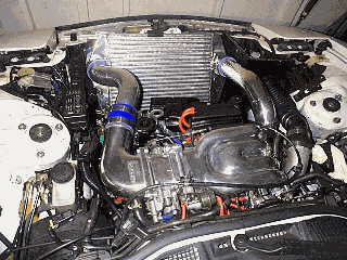
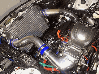
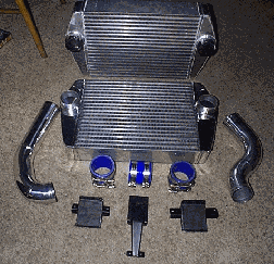
Shane Racing
Pettit
From: drchuck@petronet.net (Chuck Broussard)
PFS
From: "Rich Spear" (rdspear@hotmail.com)
Stock IC - 10.8 psi - 283.9 hp  247.7 ft-lbs
PFS IC -  11.2 psi  - 299.3 hp  264.9 ft-lbs
From: "Sam Tarbox" (Sam.Tarbox@xilinx.com)
Mazda Competition Parts
Date: Tue, 28 Jan 1997 18:39:29 +0000
From: Alex Peyzner
Blitz
From: "Emilio G. Littel" (emilio@littel.com)
> The Blitz is a work of art, but not a great value. With a 4 inch thick
> core, it should have very low pressure drop. It also may work OK with
> a slightly mod'd stock duct.
RX-7 Fashion
From: TAKESHI988@aol.com
From: Stephen J Lee
Denso
From: "Max Cooper" (maxc@speakeasy.org)
> any of you guys heard anything or used a denso intercooler on a 3rd gen or
> other??  ive had one offered to me with the specs that it
>
> Measures 20 inches wide by 13 inches tall by 2iches thick. Not a direct bolt
> on but it is easy to install and works great.Has very small dent on top of
> the first tube runner of the intercooler ,its about 1/4inch deep by 1inch
> wide.  With the endtanks it measures 29inches wide with of coarse 3inch
> inlet and outlets
Denso:             13   x 2   = 26 in^2
Stock:             11.5 x 2.5 = 29 in^2
GReddy (front):    10.5 x 4   = 42 in^2
Greddy (stock):    12.5 x 4   = 50 in^2
Other Vendors
From: "Jeff Witzer"
>Brooks Weisblat wrote:
>
> I was browsing some japanese sites and came across some pictures of
> 3rd gens that seem to have a radiator and intercooler kit that is
> together.....
>
> They are arranged in a V fashion in the mouth of the car....there is
> no duct....they come together in a way that they both form the
> duct....
>
> Hard to explain....here is a
picture.
>
> anyone know anything about this???  who makes it? how much??  and
> most importantly....is it any good?
>
> it looks good and in theory should performa well....if that IC is
> big enough....

>Kevin T. Wyum responded:
>
> Pretty interesting. Coulple of things I can't figure out. How would
> the fans fit. Where the air would discharge to in a semi stock
> engine bay and lastly would the radiator get enough air being on the
> bottom like that? Big points for creative thinking however it works
> out.
Do It Yourself
Date: Jan 4, 1999
> what I am talking about if I call and ask for the cort that ASP uses?
From: "Hung-Jen Hung"
Discussion of Front-Mounted ICs
Date: April 20, 2000
>>The intercooler duct MUST be sealed to the IC.  If not, then the air will hit the
>>face of the core and "boiunce" off of it instead of going through it.
>
>Very interesting discussion, I wonder how all this would apply to a front
>mount, like say Greddy which is in an open area without ducting.
>I wonder if the Grreddy, Blitz, HKS, etc... front mounts would benefit from
>a duct, or am I completely off base with this.
	| | | | | | | | | | | | | | | | | |
	| | | | | | | | | | | | | | | | | |
	| | | | | | | | | | | | | | | | | |
	___________________________________
	___________________________________
	___________________________________
From: Francois McKellar
From: eltang
From: "Dave Girvan"
From: NetBlazer
Intercooler Fans
From: "kevin kelleher" (kellehkj@earthlink.net)
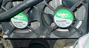
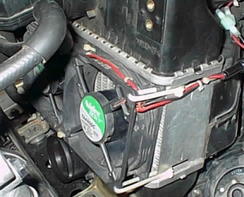
From: "kevin kelleher" (kellehkj@earthlink.net)
> I want to add a fan to my intercooler (m2 big). I don't really want it to
> run all times the car is on (I prefer a manual switch or some sort of
> temperature switch). I also don't really want to run a bunch of wires into
> the cockpit. If I do have to run wires into the cockpit, it needs to be
> very neat...............
http://www.assetmfg.com/index.html
http://www.autospeed.com/A_0589/page1.html?src=suggestions
http://www.autospeed.com/cgi-bin/browse.cgi?category=705&
http://www.autospeed.com.au/A_1043/P_1/article.html
Intercooler Ducting
April 20, 2000
Date: April 21, 2000
Water Injection and Sprayer Systems
Date: Fri, 17 May 1996 12:00:11 -0400 (EDT)
Silicone Hoses
From: "Linthicum, Sandy" (linthias@sandy-ntws.usps.gov)
Date: April 11, 2000
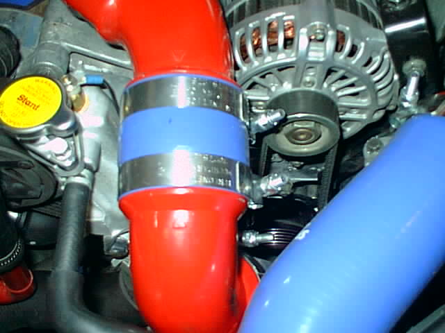
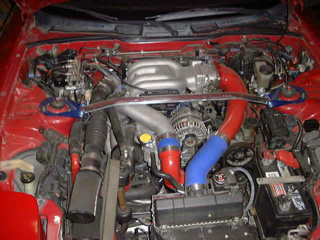
From: "Drew"
Rotary Performance
Garland, TX
972-520-3335
Signal Hill, Ca.
(562) 426-7960
http://www.mazdatrix.com/
Fresno, Ca.
(209) 438-5700
Ask for Ian and let him know what you need.
Spencer Hutchings
(714) 637-1155
Ask for Sharon Angle, say that Sandy Linthicum recommended them to you!
Glendale, Ca.
(Currently having problems with supplier, plan to buy directly from
manufacturer in the future.)
(800) 678-2886
Clamps
From: "Linthicum, Sandy" (linthias@sandy-ntws.usps.gov)
From: brad barber (bradrx7@swbell.net)
Date: May 13, 2000