Non-Sequential Turbo Conversion

Last updated: September 13, 2002

Non-Sequential Conversion

The following is from Trev Dagley's former web site, which I inherited. --Steve

_____________

Parts:

Parts I ordered when converting a car to non-sequential

Some will not be needed, like oil pan gasket, and metering oil pump O-ring. Others I ordered because the car was pre 6/92 and had many paper gaskets instead of the current metal ones. There is a * before anything that I reccomend replacing during the non-sequential conversion.

1*Oil FilterB6Y1-14-302
1*Lower intake manifold gasket:N3A1-13-111C
9*10mm nut (downpipe to turbo and turbo to exhaust manifold)JE10-40-355
9*10mm stud (downpipe to turbo and turbo to exhaust manifold)NF01-13-708A
1*8mm nut (turbo to exhaust manifold)E5B6-13-461B
1*8mm stud (turbo to exhaust manifold)N391-13-456
4*Large 10mm nut (Exhaust manifold to rotor housing)9YB1-01-0010
1Upper intake manifold gasket:N3A1-13-112
2Oil pan gasket:N3YA-10-427
1Pressure neck with capN326-15-17YA
1Fuel Recall KitN3A1-13-S70A
4Turbo compressor inlet/outlet gasketN3A1-13-712
4Turbo oil return pipe gasket Type 1N3A1-14-293
1Turbo oil return pipe gasket Type 2N3A2-14-293
4Large 10mm stud (Exhaust manifold to rotor housing) 9YA9-21-0020
1Waterpump to housing gasketN3A1-15-116
1Waterpump housing to front housing gasketN386-15-162
1Metering Oil Pump O ringN350-14-604
1TB To Upper Intake Gasket (Metal)N3A1-13-655

________________

Disassembly:

Disclaimer: Do this conversion at your own risk in every way, and your car's own risk. In no way will I or anyone else be held responsible for inaccurate information on this page or anywhere else on this site. Doing these mods will also probably void any and all engine/turbo warranties you may have.

  1. Park car on ramps, and remove the underbelly. Put it someplace out of the way, with its bolts, and two black plastic fasteners.

  2. Drain the oil, and some of the coolant...you need the coolant level to be below the lower coolant line going to the turbos. Best bet is to fully drain it. Besides it should be changed fairly often anyway as it becomes highly corrosive after 2 years.

  3. Disconnect the battery ground connection at the - battery terminal.

  4. Remove the air box, air pump.

  5. remove alternator mounting bracket (black (drivers side)) and alternator.

  6. Remove the O2 sensor connector, and wiring, and let it hang off the O2 sensor. Remove the 4 nuts holding the downpipe on. If the studs come out with the nuts this is okay, but you will need to soak them in a solution of penetrating oil to get them off without dammaging the studs. They are very expensive so be careful (1 stud is $10.40 dealer cost, and one nut is $7.80 retail cost)

  7. Remove the heat shield which is covering the motor mount. (3 10mm nuts (2 towards the back and 1 towards the front))

  8. Unbolt the downpipe from the midpipe. Remove the downpipe.

  9. Unbolt the rear aluminum intake going to the turbo and remove it out the top, and pull off the metal gasket, and save it in a safe place with the two nuts. I also label these as 'rear intake' (2 nuts on rear turbo, and possibly a bolt in the midsection of the pipe (up topside))

  10. Unbolt the black plastic IC tube coming off the turbo Y pipe and remove it.

  11. Unbolt the turbo Y pipe and remove it, then seperate the two halves, but be careful with the rubber O ring where the two pieces of the Y pipe connect. Replace the rubber O-ring if it appears baked, or there is excessive oil leakage around it.

  12. Unbolt the turbo control actuator under the turbos. (2 12mm bolts) Remove the little C clip holding the actuator rod to the turbo control gate with a small jewlers screwdriver or similar...it is okay if you dammage it cause its no longer needed. At this point you can either attempt to remove the actuator from the lines to get it out of the way, or you can leave it hanging. It might be easier in the long run to remove it completly. Its no longer needed.

  13. Unbolt and remove the EGR Valve. You will want to block this off as its not needed unless you have one with the CA switch on it. (95 cars do not even have these). If you keep it, you need to remove it anyway to get the turbos out.

  14. Take 2 17mm open end wrenches and carefully disconnect the oil line coming into the top of the turbo. Hold one nut closest to the turbo, and turn the one closest to the engine. Then leave it so the nut is on the line, but fully seperated..do not try to pull the hose off.

  15. Remove the two nuts holding the front black plastic elbow to the front turbo. Pull off the rubber vaccuum lines from the metal lines which goto the turbo control actuator, waste gate and turbo pre-control. These metal lines are held on by one of the two nuts you just removed from the plastic elbow. You will need to save the rubber lines which go into the plastic elbow, and leave in place the metal line connected to the smaller of the two rubber lines going into the elbow. This metal line is welded to the turbo oil line. The smaller of the two goes all the way up to the oil fill spout, and the larger one you will be using for vaccuum for the oil injection nossles.

  16. Remove the lower and mid heat shield for the turbos. (2 bolts and 3-4 nuts. 10mm)

  17. Unbolt the front and rear oil return lines from where they connect to the engine in the rear, and where they connect to the line extension in the front (leaving the line extension bolted to the block) (2 10mm nuts in the back, and 2 10mm bolts in the front) The front one is a lot easier to get at with the turbo control actuator removed.

  18. Unbolt the 5 14mm nuts holding the turbo on, and the 1 12mm nut, and the 2 14mm bolts from around the turbo pre-control gate cover. Leave the two smaller bolts holding the cover on (rearward of the 2 14mm bolts) in place.

  19. Remove the 2 water lines from the engine side, and leave on the turbos.

  20. Remove and lift out the turbos

  21. remove the heat shield around the exhaust manifold

  22. remove the exhaust manifold

  23. remove black plastic pressure tank (on top of engine) (no longer needed)

  24. remove the black plastic vaccuum tank from the front of the engine (no longer needed)

  25. remove the upper intake manifold

  26. remove the lower intake manifold

  27. remove all vaccuum lines (if you have a Ca car with a sensor going to the EGR valve you will have to hook the vaccuum lines back up to it.

  28. Keep lines for charcol canister including black plastic part attached to the bottom two studs holding the intake elbow on, unless you want to completly remove this system as well, which will not save much weight.

  29. If you plan to keep the airpump, or plan to use the airpump for emissions testing you will want to leave the vaccuum lines connected to the 2nd and 3rd control solenoids (the 1st being the rearward one). 2 of these lines goto the secondary air injection system on the backside of the lower intake manifold. One of them goes through a checkvalve and into a nipple on the backside of the upper intake manifold.

    Important: You should remove the vacuum line that goes from the fuel pressure regulator to the 1st solenoid valve. Then install a new line from the fuel pressure regulator to the closest manifold pressure nipple (The reccomended one is on the back side of the intake manifold, pointing towards the rear of the car, and in the direction of the fuel pressure regulator). Note that this will also make it easier to deal with the lower intake manifold since you no longer have to disconnect this line. Also be sure to glue, and tie-wrap the line in place since the fuel pressure regulator vacuum nipple has NO barb on it. If this line pops off, you will run lean, and possibly blow your motor which is the primary reason for simplifying the vaccuum line routing!

  30. On a clean workbench:

  31. Remove the C clips from the pre-control gate and wastegate.

  32. Unbolt the pre-control actuator from the front compressor housing and throw away.

  33. remove the front and rear turbo compressor housings(6 10mm bolts each)

  34. remove the front and rear turbine housing (4 13mm bolts each)

  35. Send out the front turbine housing for wastegate machining, It should be bored out to 1.24" using a Mill, and make sure they know enough to center the hole with the gate (if they don't you do not want them doing any of your machining anyway)

  36. Open the pre-control gate approx 90% and have welded in this position (you want the gate to be opened and be even with the turbine chamber flow path..IE less exhaust drag). The weld goes around the base of the lever that the pre-control actuator clipped to. DO not weld on the inside of the turbine housing in any way, shape or form, and do not simply tack this as it could come loose.

  37. Take the exhaust housing and grind off the gate's outside lever, and then the welds from the washer which is welded to the exhaust manifold. The washer should either fall off, or can be pried off. Then drive out the sleave (from the inside going out towards where the washer was) and lift out the control gate and throw away.

  38. Using a 3/8" - 18 pipe tap, tap out the hole the sleave was in, and install a CAST IRON 3/8" pipe plug. Do not use a forged steal pipe plug or cracking could occur due to differing expansion rates of the materials.

  39. Take apart the turbo Y pipe, and remove the butterfly from it, and its control actuator, etc. Install an aluminum blocking plate in the control actuator's place. Block off the vaccuum nipples with 3/16" vaccuum caps glud on 3M 8000 (might be 8001) gasket sealer and tie-wraps.

  40. You will also want to do the same to the secondary throttle control butterflies in the upper intake manifold.

________________

email:

Disclaimer: Do this conversion at your own risk in every way, and your car's own risk. In no way will I or anyone else be held responsible for inaccurate information on this page or anywhere else on this site. Doing these mods will also probably void any and all engine/turbo warranties you may have.

You will *need* to open up your wastegate from the on paper 1" diameter to
1.24". Use a mill to do this, don't waste your time with a die grinder as
some people who obviously have more time on their hands than common sense,
or money to pay a machinist have done :)

The mill has the added benefit of allowing you to align the hole with the
flapper, which is something the stock hole is not. (IE off center some
whgich is not a problem with a 1" hole, but 1.24" would be)

The Turbo Pre-control gate should be welded open. The weld goes at the
base of the outside control arm, and should be welded good, not just
tacked. (preferably TIG welded, but a good wire feed is acceptable for
this)

The turbo control gate in the manifold has got to be removed and the hole
tapped for pipe threads, and a cast iron pipe plug installed.

To remove, take a cut off wheel, or a 4" disc grinder and cut the control
arm off at the base, then grind the welds off and remove the outside
washer, then from the inside tap out the sleave the flapper shaft rides
in, then the flapper valve and shaft will come out from the inside.
DO not even think about welding this one...do not leave it in there...it
absolutely has to come out!

The solenoid valves will all stay in place. If you have a CA car leave the
EGR vacuum line attached, or run a new one. All other lines should be
removed.

The MOP lines should be saved, and the metal mass of metal lines which
they connected to should be removed, and seperated. You want to keep the T
arrangment that the MOP org. connected into as its perfect for this.
Connect the MOP nozzles to the T (just like stock) and tie-wrap the T to
the solenoid valves. Run a new vacuum line from the T down to the vacuum
orfice coming off the front turbos inlet elbow (there are 2 orfices
there...one for vacuum for the vent on the oil filler and one for the MOP
vacuum)

The only other vacuum line you will need is for the fuel pressure
regulator. Take a line that has a molded U shape in the end, and run it
from the fuel pressure regulator, around the inside of the lower intake
manifold, and connect it to the Vacuum nipple which is facing rearward at
an angle.

Vacuum cap all the other vacuum nipples, and you may even want to remove
and cap off the PCV valve as its not needed (95 RX7 comes stock with this
capped off on both ends where it used to connect which I was already
doing before I saw a 95 rx7 :)

The wastegate control actuator itself should be connected to an
aftermarket boost controller, or a manual bleed valve (like one the paint
guns use)

The butterfly in the turbo Y pipe has to come out, and a blocking plate
installed in its place. You should also remove the butterflies from the
upper intake manifold as they will not work with your new arrangment.

Both black canisters (vaccum and pressure chambers) should be tossed, as
well as the large turbo control actuator, and turbo precontrol.

Blocking Plates For Non-Sequential Conversions


These are 1/8" thick band saw cut aluminum. Just trace the outside of the gaskets, then cut. The same for the gasket material...that was made from the make your own gasket sheets you can buy at any auto parts store. One thing I was not clear on...leave the solenoids in place and electricly connected. The same goes for the large solenoid array bolted to the back side of the lower intake manifold...I make a large blocking plate for it, and leave it in place (you will have to remove the one way circular valve, to get the blocking plate in there) All those sensors and solenoids stay connected electrically as well, but all lose their vacuum lines. The MAP sensor of course keeps its line. The two Blow off valves should have their vacuum lines teed together and tapped into a vacuum nipple on the passenger side of the upper intake manifold. You now will have 2 BOVs working together instead of the 1 + somthing alltogether different in function at least. If you run into any questions feel free to email...just use common sense, and if in doubt, remove it, and block off where it was...if its not electrically connected, then its usually not needed. Trev FTL Racing

________________

From: Westbrook, Chuck E. (CWestbrook@tmh.tmc.edu)
Sent: Monday, March 06, 2000 12:00 PM

This weekend, I tested out my new non-seq setup with a down pipe, mid pipe, cat back, and using Rick Sheveland's ECU. Normally I run a hi-flow cat but mine is dead and am waiting for the new one to arrive. I currently don't have an electronic boost regulator, using a manual valve. Using the manual for non-seq boost control causes an unusual boost pattern. Evidently the duty cycle for the wastegate solenoid is lower below 4500 rpm then becomes higher. This allows more boost below 4500 rpm and less above. With the valve adjusted for 14 psi max boost, my curve in 4th and 5th gears were like:

0000 - 2500 rpm, vacuum
2500 - 4000 rpm, boost building
4000 - 4500 rpm, 14 psi boost
4500 - 7500 rpm, about 12.5 psi boost

I also ran with max boost set at about 13 psi, after 4500 rpm, boost dropped to about 12 psi.

Conclusions:

  1. Non-seq with no cats will make max boost somewhere between 3500 and 4000 rpm. I will try to get a more accurate rpm where max boost occurs.
  2. You need an electronic boost controller if you want to keep max boost above 4500 rpm the same as below.
  3. The exhaust was not louder with non-seq as compared to seq.

When my new hi-flow cat is installed, I'll again give the test results. After experincing the POWER of 14 psi with a mid-pipe, I just might have to get new chips for my ECU!

_________________

Date: Tue, 7 Mar 2000 05:37:40 -0500
From: "NICK RIEFNER" (racin@att.net)

Chuck, you can take out all of the solenoids and run two needle valves in their place. Put one directly in the line from the nipple on the turbo that provides the boost signal and run it to the wastegate actuator in the normal fashion. This will control the rise time of your boost. Put the other one on the other nipple of the actuator or 'push' side of the wastegate actuator, and vent it to atmosphere. This one will tell the actuator how much boost it is receiving. This is the one that you can fool the actuator with, to make more boost if you want to by opening the valve slightly. Start with the first one opened two or three turns, and the second one closed. Because of my turbos, intake, and the exhaust I'm using, this one stays closed for me, so I'm really relying on the wastegate spring. Even with the wastegate ported, I'm seeing more boost than I would like. You can get the boost to come up pretty quick with this setup, using the first valve to regulate how quickly the actuator is filled with boosted air. Use resistors to fool the computer into thinking that everything is working as it should. 300 ohm should suffice.

_______________

Date: Mon, 06 Mar 2000 13:20:50 -0500 (EST)
From: KELLEHKJ@esvax.email.dupont.com

> (2) You need an electronic boost controller if you
> want to keep max boost above 4500 rpm the same as below.

Maybe not.

If you want to run steady boost, put stock pill (.063) back in. Disconnect the vac line to the stock sol valve, and put in the man valve, bleeding to the atmosphere. You replace the stock variable controlled vent with a fixed, adjustable one. Start closed, and open about 1/8 turn at a time.

For info on stock sol-valve maps, see my notes on Rob Robinette's site.

_________________

Date: Mon, 22 May 2000 02:23:07 -0700
From: "Diep, Anh" (diepat@earthlink.net)

I did a quick thumbnail page of my Turbos converted for Non-Seq operation right before sending them to Turbo City for a rebuild.

If anyone is interested I took some pix. I haven't added any information other than the pix themselves but will do so tomorrow night which will include; bolt sizes, welding, porting, basically what goes where. http://members.xoom.com/diepat_rx7/rx7/non_seq/turbo/Page.html

________________

Date: Wed, 14 Mar 2001 13:51:58 -0600
From: "Westbrook, Chuck E." (CWestbrook@tmh.tmc.edu)

For the experienced FD owner/mechanic here is some details of my conversion last year. A well done conversion is the key to success!

CONVERSION FROM SEQ TO NON-SEQ TURBOS, NON DETAILD

MINIMUM MODS REQUIRED FOR FAIR LOW END RESPONCE:

MODS THAT FURTHER INCREASE RESPONCE:

CHANGES:

With all of the above mods except MP and intake porting, and still running the air pump; low end response is better than a stock FD except in 4th or 5th between 2500 and 3000 rpms. Using the gears properly, nothing is lost, and much is gained. In day to day driving in Houston traffic, I normally do not go over 3000 rpm in 1st through 3rd and drivability does not suffer.

________________

Date: Wed, 14 Mar 2001 16:04:21 -0500
From: "Wade Lanham" (wadelanham@hotmail.com)

Excellent information! I would like to add a few comments, though I am certainly not a non-sequential expert.

All the unused nipples on the Ypipe and upper intake manifold should probably be removed and Tig welded over. It's a shame to remove all those hoses and then just put a cap over the nipples, since they can break/leak too. Some of the nipples (all?) are press-fit into the aluminum, so they will need cut/drilled or pulled out before Tig welding over the holes.

Also, more importantly, it should be mentioned that it is usual for people who have made this conversion who have no cats to have BOOST CREEP, even with a ported wastegate! This is highly important, since boost creep can be a bigger problem than a failing sequential system!

Most of these people end up installing RESTRICTIVE exhausts to keep the boost under control. All that work to improve efficiency is wasted if this is the case. This is probably the biggest reason I still have the sequential system.

Non-Sequential Boost Control

From: kyle krutilek (twok@hotmail.com)
Sent: Wednesday, January 26, 2000 11:29 PM

Nice thread on the non-seq conversion, here's a question for the gurus

What boost controller are the non sequential cars running? I wonder if the new AVCR boost controller can help reduce the turbo lag as compared to a Profec B or other popular controller.

_______________

Date: Thu, 27 Jan 2000 00:03:47 -0500
From: "Ryan Schlagheck" (ryan.schlagheck@worldnet.att.net)

First, to frame your question, we're talking about using a boost controller to keep the wastegate closed longer to allow boost to build. I've all but given up using an electronic boost controller to keep upper boost to a sub-14psi preset level on a non-seq car. On non-seq cars, I found that the easiest way to limit boost was to plumb a line off the wastegate diaphragm to a certain length. Doing this, I was able to use three lengths of hose to run 10, 12 and 14 psi. In the winter, I kept it on 12psi, for those 40-degree nights. This works for the upper end of boost control, to limit boost.

To spool boost faster on a non-seq car, since a proper non-seq requires grinding the wastegate and clipping the primary, we no longer have as many physical restrictions that keep backpressure in the manifold for a split second longer like the sequential setup. For this, I had Mandeville Auto Tech install a small spring, actually a pedal return spring for a clutch, onto the wastegate rod. The wastegate has an internal spring that begins to compress at 7psi, then is fully open by 9.5psi. By attaching a "helper" spring, additional pressure is required before opening the wastegate fully. By placing a row of holes where I can clip in one end of the helper spring, I can change the tension required thereby necessitating more boost before opening the wastegate. It's not elegant, but it does help me spool faster. As an aside, one of my goals for the car is to get it to react as quickly off the line as a sequential car, mostly for 1/4 mile action. WIth the lightweight flywheel and this mod, all I need to do is sort out my ignition/fuel problem and I'll be able to check it out.

I have not been able to find an electronic boost controller to control/adjust boost on a non-seq setup the way my low-tech solution does. Not to say that my way is the best way. I'd love to be able to adjust boost between street driving, those occasional on-ramp drags, and track sessions.

______________

Date: Thu, 27 Jan 2000 10:48:01 -0500 (EST)
From: KELLEHKJ@esvax.email.dupont.com

For non-sequential, I would think the Hallman controller would work well.

Good reports from 10 sec DSM users. Contact Marc Hallman, at website below. It should provide quicker spool up than the long hose method, that does progressively open a double springed WG. Yes, simple relief valve, but he has got it sized to work right.

(Your xtra parallel spring idea is much better than excessively increasing preload on existing spring...resulting in lost motion at the flapper valve)

Non-Sequential Simplification

Date: Sun, 30 May 1999 20:02:03 -0400
From: Sandy Linthicum (sandy_linthicum@mindspring.com)

You can convert to non-seq without taking the turbo off by simply disconnecting 95% of the control system and wiring the precontrol stuff fully open or closed (ie. deactivate everything but primary wastegate.

This gives you 95% of the non-seq total mod but still let you go back to seq with no sweat. Lets you get a feel for how it works and responds and if you do not like it you can go back to stock. main advantange for most of us of non-seq is simple operation and reliability - plus drasticly reduced cracking of the exhaust side turbo houseing due to constant heat cycling of of seq control. Turbo control becomes 1000% simpler to troubleshoot to the level that even I, after lots of study etc can do it myself. There are only a few shop in the us that really understand the seq system and can keep it working right. If you do not live near one of them then you have some tough choices to make.

If your seq system is working OK now, leave it alone till you have trouble.

Disadvantage is you need to dump the CATs to make it work well (you need the higher flow to reduce lag plus an open intake), its makes the car louder and instant 10-12 psi boost at 3000rpm is history - boost build slower (not really lag) and its about 4000 or more when its full bore. For no-brainer street performance the seq is hands down better.

I ran 2.5 yrs with the kluged up non-seq with no problems. When you permanately mod it to nonseq by physically removing and machineing/welding out the seq stuff you improve turbo eff so much that just about everyone who does this has boost control problems (ie. at 6000rpm and up you cannot keep boost under 14psi because you have exceeded what the wastegate with all reasonable mods & enlargements can handle.

_______________

David Liberman (david@rx-7.net)

And, if you run non-sequential, use the charge relief valve as a second blowoff valve. Just T it into the line to the primary valve, and it will vent the secondary turbo better than the ABV will.

________________

Date: Sat, 29 May 1999 13:17:12 -0700
From: "Brian L. Goble" (goble@lith.com)

I am in the process of converting to non-sequential with the help of Jim, Justin, and Trev. I slapped up a quick page with 10 pictures. This is part 1, where everything necessary is off the car (and on my garage floor). I hope these pictures are interesting to some of you who maybe haven't seen the turbos and exhaust manifold before.

________________

Date: Thu, 13 Jan 2000 11:14:20 -0800 (PST) From: Mark Valskis (mvalskis@yahoo.com) Subject: Re:(rx7)[3]sequential simplification? (emissions elimination)

> I have reason to believe the sequential control system can be
> simplified, but still function the same as far as boost pattern.
> Do any of the control system experts on this list know of a way to
> remove hoses and solenoids that aren't absolutely necessary for the
> operation of the sequential system?

Sequential simplification isn't really a valid title, since you are not talking about affecting any of the sequential control hardware.

That said, at least half of the solenoids and a lot of the rat's nest is due to emissions controls. If you don't have to deal with emissions at all, you could get rid of these things and reduce the bundle and clutter substantially. If you are still running the factory ECU, you would have to wire in resistors to the wires that used to connect to the solenoids so that the ECU didn't trigger an error code. The list of solenoids which control the emissions are as follows:

Purge Control Solenoid
Relief1 Solenoid
Relief2 Solenoid
Port Air Bypass Solenoid
Split Air Bypass Solenoid
Switching Solenoid

Additionally, you could disable the accelerated warmup system and eliminate the AWS Solenoid.

You would be left with:

Idle Speed Control Solenoid
Pressure Regulator Control Solenoid
Turbo Pre-Control Solenoid
Turbo Control Solenoid
Charge Relief Solenoid
Charge Control Solenoid
Wastegate Control Solenoid

_______________

From: Wade Lanham (walanham@mountaineergas.com)
Date: May 10, 2000

See the following diagram:

Turbo System

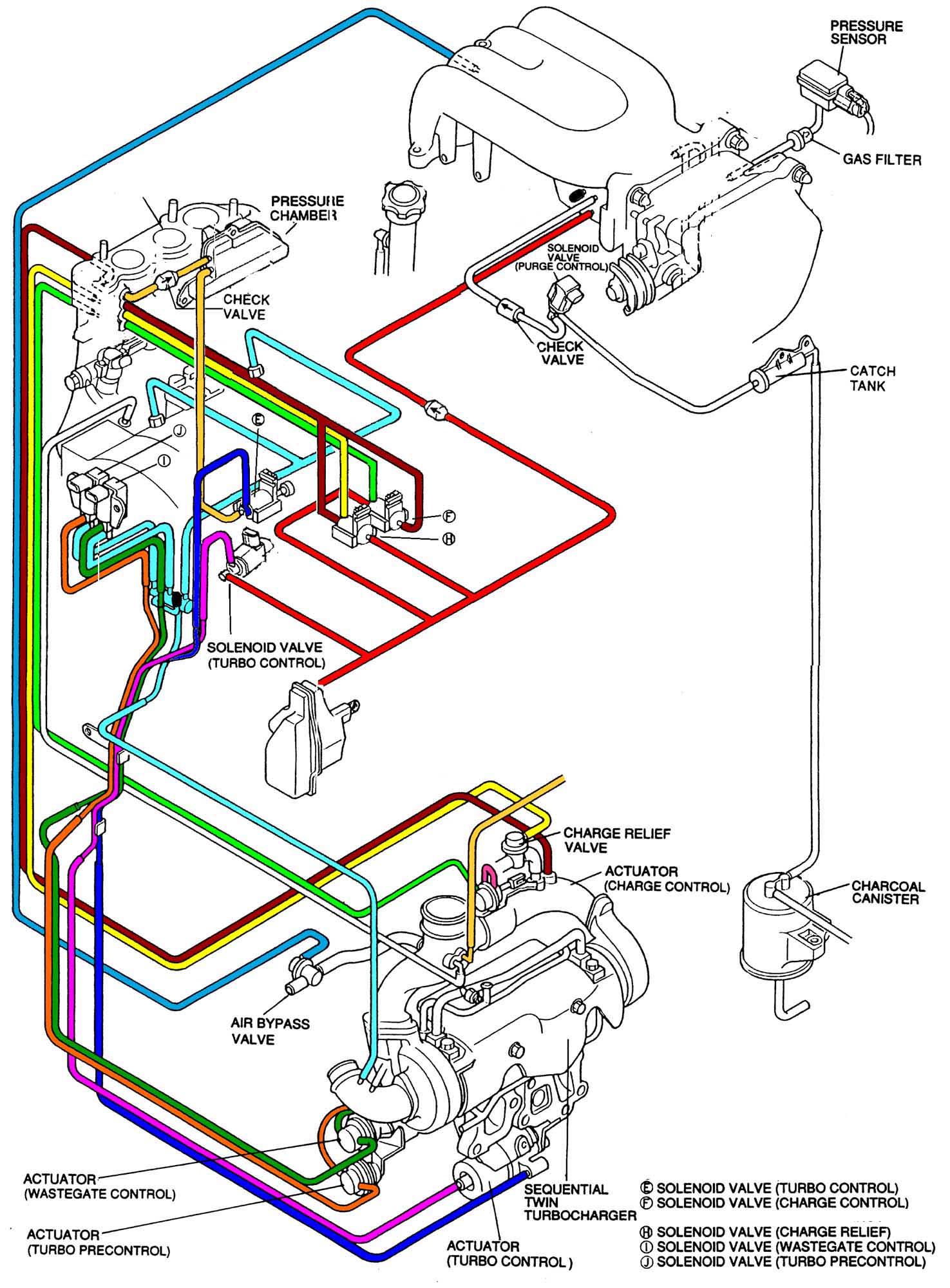
The parts are in their approximate position on my car.

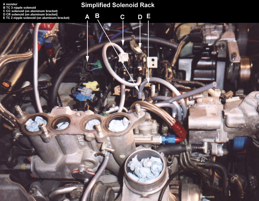
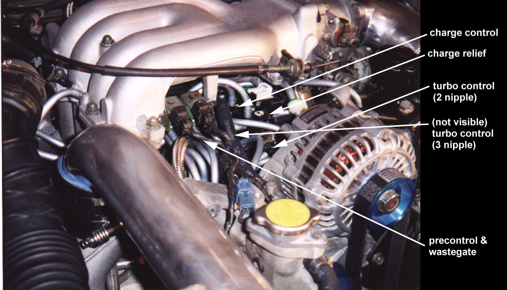
See the following photos:

Turbo System - simplified picture 1Turbo System - simplified picture 2

I made this change because I wanted to keep the sequential system for now, but I wanted the car to be easier to work on and look cleaner under the hood. I envy the non-sequential look. :)

"Thanks" to Mark Valskis and Derek Vanditmars for answering questions, and Mike Putnam for putting together the "turbo control systems ONLY" colored diagram.

The ways I succeeded:

  1. The system is very simple now - there are few enough hoses and solenoids that I know where they should connecte and what they do.

  2. The engine looks marginally cleaner fully assembled, and much cleaner with the upper manifold removed (where the lack of solenoids/hoses really shows).

  3. Almost every hose is easy to see and reach without removing ANY parts. I placed the solenoids and most hoses just behind the alternator but in front of the upper manifold. If a hose does pop off, it shouldn't be hard to fix.

  4. I have a box that weights about 15 lbs that has nothing but stock "junk" hoses, tubes, valves, etc.

The ways I failed:

  1. The engine looks only marginally cleaner when fully assembled.

  2. There are still approximately 25 vacuum hoses.

  3. My car runs poorly when cold (I think this is because of the fast idle cam removal - I'll know for certain soon).

Notes:

  1. In the diagram, I show nothing for the fuel pressure regulator. I did some fuel system work at the same time as the vacuum system which included an aftermarket fuel pressure regulator that I attached to the nipple on the bottom of the lower intake manifold (same source location as stock but with only one hose.) You MUST leave the stock system intact OR add an aftermarket pressure regulator of some kind. For those not modifying their fuel system at this time, be SURE to have the FPR solenoid and lines attached well and correctly (failure of any of these parts could easily cause engine failure).

  2. I left the colors the same as Mike Putnam's (?) colored flow diagram and system diagram. His diagrams were essential for me to make these changes to my system successfully. I recommend printing both of his diagrams and mine if you plan to perform this modification.

  3. For the Charge Control Solenoid and Charge Relief Solenoid lines that T, and the oil metering vacuum line T, I used some plastic Ts from the local auto parts store. For the Vacuum Chamber connections I used 5-way that has a nipple on each end and three nipples coming off the side. I removed all other metal tubes and Ts except for the tubes running down to the intake elbow and the turbo actuators (it is left in the diagram) because it seemed like removing these would make the area cluttered with silicon hose instead.

  4. I removed all the metal hoses for fuel/coolant. All the coolant lines were replaced with one that runs from the back of the block to the filler neck in a straight shot. All the fuel lines were removed because I tapped the injector rails and used braided stainless. Most people will probably be leaving all of these fuel and coolant lines stock.

  5. I removed all of the solenoid "Rack." The rack was replaced with a small piece of aluminum that now holds the CC, CR, and the TC actuator (that is normally on the ACV). The new AL rack is attached to the upper tab on the coil box. There are two of these - I think they might have been attached to the original rack (?). The Pressure chamber is mounted upside down where the ACV used to be. You could put it wherever you want. The other TC black solenoid rack valve is located in between the new rack and the lower intake manifold in approximately the same position as in the diagram.

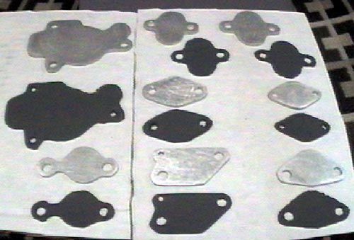
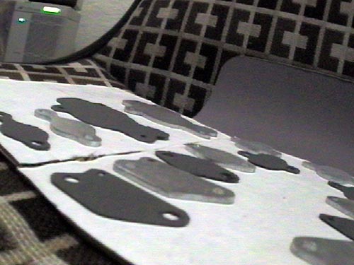
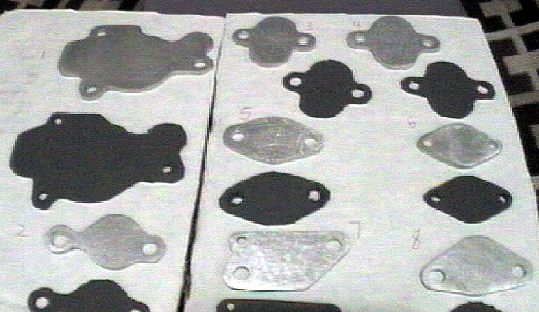
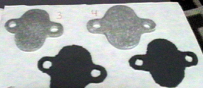
  6. I removed the ACV, EGR, DT, AWS, and Fast Idle cam. I probably should have left the fast idle cam, because my car now runs like crap when it is cold. These parts were replaced with blockoff plates and any solenoids that would cause error codes were replaced with the appropriate resistors attached to connectors that would slide into the original harness (I didn't really want to cut the stock harness up at this point). You can get the resistance of the solenoids from the workshop manual. If anything, go a little on the high side.

  7. I left the uncolored hose (in my diagram) on my car. I meant to remove it, but forgot until it was inconvenient.

  8. I left the fuel evaporative system intact at this time, sans some of the unnecessary plumbling.

  9. I rewrapped a lot of the main harness because the shrink wrap shattered when I moved the harness around.

  10. I removed the nipple for the PVC from the manifold (capped the filler neck nipple), and the double throttle plates and related hardware. I tapped both manifold holes and plugged them.

  11. The orange line that seems to go to nowhere goes to the upper intake manifold (it should be obvious, just thought I'd mention it before someone asked).

  12. I used one of the nipples on the back of the intake manifold for my boost gauge.

I think that's it for now. As I think of more, I'll make adjustments to the diagram and this document. If you have any suggestions or question, just leave me a message. I'm not very busy this week at work (if you couldn't tell already from the length of this message).

Non-Sequential Kit

Date: Thu, 14 May 1998 18:54:09 -0700
From: Trey Cobb (trey@rx-7.com) Hello all! Sorry about bringing up a "commercial" subject on the list but you guys/girls always give good input so here it goes.

We're thinking about offering a Non-Sequential Conversion kit that would include a modified, ported manifold, possibly ceramic coated, with all the instructions and additional pieces needed to convert the car from Sequential to Non-Sequential operation. We'd offer the kit on an exchange basis for your old manifold.

Cost would be approximately $300-$400 and would be great for someone that wants to perform the conversion over the weekend instead of having the car down for awhile getting the parts modified.

We're aware of the controversy about Non-Sequential vs Sequential but for those that are looking to do the conversion, this might be a simple method of doing it.

Please email me directly with any comments and/or suggestions. Thanks!

Trey Cobb                               trey@rx-7.com
Rotary Performance - Online!    http://www.rx-7.com
Garland, TX                             972-530-3335

_______________

Date: Fri, 15 May 98 06:59:50 -0500
From: "Linthicum, Sandy" (linthias@sandy-ntws.usps.gov)

My personal opinion, way too high. Not only expensive but you are skipping the important part needed on the turbo - making the wastegate bigger, welding and/or grinding out the restriction/controls that are not used with nonsequential but without moding the turbo both get in the way and cause restriction and/or can still fail and cause a problem.

Much more reasonable to ship your turbo & manifold to Pettit overnight, have him mod & blueprint/rebuild and get it back overnight.

[ Mail me ] [ To Lightning home page ] [ To my home page ] [ Copyright Notice ]