
Date: Mon, 27 Mar 2000 12:34:17 -0800 I just got off the phone with Turbonetics and Turbo City
Basically Turbonetics gave me a price of about $702 to rebuild both turbos,
which include; (forgot to ask about warranty)
$175 each turbo blueprinting, balancing, VSR, Five Day Turnaround. But I have to send it through a dealer, which Tri-point
is and it shouldn't alter the price. I haven't confirmed with Tri-Point yet.
Turbo City gave me a price of 588 for both turbos same as above but they
don't do VSR but use other methods of tunning for vibration and do not clip
compressor wheels for adding the extra air flow. One Day Turnaround. They
have a 3 month/3,000 mile warranty.
I am not in a rush because I have a daily driver and for what I care please
take your time!! I've had bad experiences because of me rushing my mechanic
on a clutch job.
I called Mazdatrix and they really recommend Turbo City. They send all their
Turbo rebuild jobs over to them and to their knowledge have no complaints.
________________
Date: Wed, 09 Jun 1999 02:48:32 -0400 I called some shops today and got info on the upgrades available for the
sequential (stock) turbos. I will be out of town for a few weeks, but I wanted
to get a quick list together for those that were interested.
There are a few more options out there, but this should be a decent
survey of what is available. I don't know what I want yet. I welcome any
corrections, comments or additions.
________________
Date: Wed, 30 Jun 1999 02:20:05 -0400 I have been looking at upgraded sequential turbos lately. I heard from a
lot of people that the shafts tend to snap with bigger compressor
wheels. Some say this is only a problem when you run 18 psi, but others
said it is a general problem which I assume can happen at lower boost
levels. Any testimonials out there to help us understand?
Rotary Performance Online has an upgrade that uses
Garrett compressors AND shafts. This sounds like a durable upgrade, but
it is expensive ($3100). RPO seems to be the only vendor that offers
such an upgrade.
Clipping the exhaust turbines means less backpressure for more power but
also more lag. How much? I don't know.
Personally, I am leaning toward saving money and getting a standard
rebuild. I think you really have to decide what you want out of the car
before you spend a lot of money on a fancy sequential upgrade or a
single turbo setup. I am not totally sure what I want yet.
Here's a short list of what is available:
* Various levels of warranty
* A large range of prices for what seems like the same thing
________________
Date: Thu, 6 Jan 2000 11:50:28 -1000 (HST) It really depends on what your looking for. Maximum responsiveness, enhanced
reliability, maximum bang for the buck or ultimate power potential.
I'm not sure but I believe that the upgrades only flow at most 20% better
than the stockers (not really the same thing as efficientcy but will have to
do). Not much gain there compared to something like a T-66 or T-78 single
with nice big exhaust manifold . A major weakness of the stock setup is of
course the restrictive and fragile exhaust manifold and turbo housing. Ever
look at them? Fine for 14 lbs of boost on a near stock motor expected to put
out no more than 360 RW HP (maybe 385 if you go non seq, hogg out the
manifolds and pay very special attention to your fuel system). Still
ultimately hopeless for really high flow situations when looking for 450+
hp. Too much back pressure for really efficient high boost no matter how
good the upgraded turbos are. I certainly would strongly consider sticking
with the stockers without the upgrades if I just wanted 360 hp. and a very
responsive street car for a reasonable investment. If the seq. transition
bothered me (and believe me it can be quite dangerous at 360 hp) you can
still just go non seq. The upgrades though seem just to little bang for the
buck, being as pricy as a good single but with less ultimate potential stuck
with the crappy OEM manifold/housing. And, unless you go non seq. your still
stuck with the rat's nest of stupid vacume lines, control actuators,
pre-control actuators/valves, solenoids etc.
A most interesting comparason would be between upgraded OEM non sequential
turbos vs a well set up dual BB single system. Hmmmm, all things considered
I'd bet on the single to be just (or darn near) as responsive, price
competative and with more maximum potential.
Date: Tue, 18 Jan 2000 15:06:15 -0500 (EST) > What is the purpose of upgrading the turbocharger, it's efficiency in There are three things that trade off against each other with a turbo.
Lag, airflow (measured in CFM), and boost. You can improve any of these
but the other two suffer. If you want to improve all three, then your
turbo must work harder, which reduces its efficiency. This translates
into increased temperature and more "effort" expended to produce a given
amount of boost. Turbos have an efficiency range in which they work very
well within certain boost and CFM parameters, but rapidly become very
inefficient outside those parameters. Typically, a bigger turbo will have
an efficiency range better suited to high boost, high flow.
> How can a turbocharger help increase horsepower other than by increase By increasing the airflow. Improvements in VE (such as by opening the
intake and exhaust, or by porting) and higher RPM operation require more
airflow. Sometimes they happen together. For example, a street port not
only improves efficiency, but also moves the HP peak up in the rev range.
This requires the turbo to blow more air on both counts.
> What are the components of a turbocharger anyway, compressor wheel, Mostly the important components are the compressor/impeller, the turbine,
and the housing. The housing determines how fast the air blows into and
out of the system, (a smaller housing accelerates the air in the turbo
making it spool faster, but also provides restriction). A smaller housing
is better for low (engine) RPM operation and worse for high RPM, even with
the same compressor and turbine. The shaft connects the compressor to the
turbine but as long as it doesn't fail it makes no difference from a
performance standpoint. The turbine and the compressor sizing determines
the maximum output, but larger means more lag and more difficult boost
control.
> either by replacing parts, or replacing the whole thing?
Typically the whole turbo is replaced, although it is (theoretically)
possible to change the parts individually.
Editor's note: See the section above on
upgrading the stock turbos
for more info on what parts are typically upgraded or replaced. --Steve
_______________
Date: Tue, 18 Jan 2000 21:16:36 -0500 Three reasons to upgrade the turbochargers on the 3rd Gen. Efficiency,
reliability, and power. That's the simple answer. Let me try a brief
explanation.
Efficiency, Power
All turbochargers present compromises between flow capacity and turbo lag.
The larger the turbo, the slower it is to spool, but the more air it can
flow when up to speed. The FD's units were sized for maximum response while
meeting the flow requirements of the engine at the targeted power level.
Each compressor has an area of greatest efficiency (adiabatic), in which it
can compress/flow a given volume of air per unit time without introducing
excessive heat in the process. This is defined graphically by a compressor
map, and is primarily a function of compressor design, size, and rotation
speed. Increase flow to obtain more power on the FD by adding intake,
exhaust, intercooler, etc.and you will rapidly find yourself outside the
stock turbocharger's efficiency sweetspot, since the compressor must spin
faster to maintain the same intake pressure. The main detriment in the
11-13 psi range is that the compressor outlet temps become extremely hot,
on the order of 300F, which places additional thermal stress on the engine,
and may increase detonation risk. Also, in sequential twin-turbo cars, the
secondary unit is accelerated to a high speed in a closed circuit chamber
(surge) to prevent a drop in compressor speed and flow at the switchover
point when the compressor comes under load, which would cause a dip in
power and torque (the famous dip we all notice in the dyno plots). This
power dip, already slightly noticeable in stock cars, becomes much worse in
modded cars, since the turbo is already operating at its pre-spin speed
just to maintain a given level of boost, and becomes extremely resistant to
overspeeding.
Over 14 psi on sequential twin cars with fully open intake and exhaust, the
stock turbos actually cause a restriction in the intake path which limit
the effective power you can make. Can you upgrade to larger compressor
wheels? Sure, but shaft failures often accompany this mod, because the
stock shaft was not sized for that weight wheel. You can also clip the
turbine wheels for better flow at high speed, but low speed response may be
impacted. The switchover problem does not go away.
So, the guys who want BIG power (360 RWHP +) go to a single, large turbo.
And they throw in a whole new fuel system just for kicks (also happens to
help keep the engine alive). What they gain in power, they lose in
response. Drag racers don't care about this because they can pre-load the
turbo off the line, use NOS, or some combination of the two, and benefit
from tremendous increases in top-end power. Road racers (especially those
who drive tight courses) do care, because the car is either way too fast or
way too slow (just like the old Porsche 930 Turbos). For them, nothing
beats the response of the stock sequential twins.
In terms of reliability, the stock system is extremely complex, not very
durable, and most people have no clue how to troubleshoot it. The nest of
vacuum hoses and solenoids has driven many an at-home mechanic to the brink
of suicide. Even when it does work, it is not entirely consistent in its
operation, to put it politely. So you may be left wondering where your
second turbo is as you watch Jim's Supra blow past you (probably would
anyway). Bad as that is, increasing boost on the sequential system seems to
present problems for piggyback boost controllers which are totally beyond
the scope of this post (to the extent the post is not already beyond its
own scope). The PFS-PMC seems finally to have overcome the majority of
these problems but it has taken six years! The solution to this melodrama
for some, is to go single turbo: one wastegate, one boost pattern, no
vacuum nest, no solenoids, theoretically easy fuel map etc. So say the
single turbo guys. And their results at the strip corroborate this view.
Me, I like the twisties, so I will stay twin-sequential for now, for the
response. My next upgrade will be either a 20B twin-sequential, or 5.7
liters of V-8 power in something that looks sorta like an RX-7 from the
front ;-)
_______________
Date: Tue, 18 Jan 2000 21:49:41 -0800 Let me start by saying that everyone who intends to modify a
turbo-charged car should buy, read, and refer to the book
_Maximum_Boost_ by Corky Bell. It is a little dated, but the
fundamentals are still the same and this book is a very readable and
practical introduction to all things 'turbo'. Highly recommended. Buy it
at http://www.amazon.com/.
> What is the purpose of upgrading the turbocharger, it's efficiency in Most turbo upgrades are performed to increase peak power, often at the
expense of low end power. The average turbo upgrade increases lag. It is
up to the purchaser to decide what they want to optimize. There is no
turbo that will offer the least lag and the highest maximum power, it is
always a balance. Some turbos are "better" than others in that they
offer a little more of both than a less good alternative.
> How can a turbocharger help increase horsepower other than by increase the There are several ways this can happen. First, you might actually reduce
lag and increase low end power if you select a turbo that can create
high boost pressure at a low rate of flow. But usually, just as you
suggest, you get a turbo that can produce more boost at high RPM (high
flow). Another important factor is compressor efficiency. Compressor
efficiency is a measure of how much the turbo heats the air at a given
boost and flow rate. Greater efficiency (less heating) gives you greater
power as the air that comes out of the turbo is more dense with air
molecules. It is like driving your car on a cold night -- it makes more
power. It also does not have to work as hard to create that level of
boost, so you will have less backpressure being caused by the turbo. We
all know how important a free-flowing exhaust system is on a rotary, and
having an efficient turbo system is especially beneficial for the same
reason.
> What are the components of a turbocharger anyway, compressor wheel, shaft? You basically have the turbine side that is driven by the exhaust
gasses, a shaft and bearing in the middle, and a compressor side that
compresses your intake air on the other side. The turbine and compressor
parts include both a wheel and a housing which give them their
performance characteristics. The shaft's diameter is important in the
case of the third gen, because it is too small to support large
compressor wheels. Most turbos use a regular bearing, but ball bearing
turbos offer reduced lag and perhaps increased reliability.
_______________
Date: Fri, 13 Mar 1998 00:07:17 -0500 You might want to check out Turbo City
out in CA. I've recently sent for a catalogue and if I remember correctly
(I'm at work now, so I can't look it up), they have replacement
"cartridges", rebuild kits, rebuilt turbos, and I think even new turbos
for the 3rd gens. They also have rebuild kits and rebuilt turbos for the
2nd gens for all of those who may be interested. Of course, they have
some aftermarket stuff too.
_________________
Date: Wed, 28 Apr 1999 23:49:02 -0500 You can use any of the following turbos I listed below:
T62-1, T60-1, TS04, T66 W/ceramic ball bearing
Any of those turbo should work well on rx7. The only reason I pick T62-1 is
that it has a relative good flow rate. T60-1 will give you better low end
response(Marcus from Apex racing has dynoed 380rwhp@12psi with this turbo).
T66 will give you high end horsepower (actually has a better response than
the T62-1 if you have the ceramic ball bearing). My friend Brent Bucher
dynoed at 399rwhp@17psi using this turbo on a stock motor. He gets full
boost at 4krpm vs. 4.5krpm on my turbo.
The only main difference between the
setup between my car and the guys i mention above is that I'm still using the
stock injectors but both of them are running stock motor and 3.5in exhaust
system. I guess there're some gain for running a bigger exhaust system. The
reason why I decided to use the T62-1 is because I'm cheap and didn't want to
spend too much money for trial and error not knowing what to expect. It's
really up to you as to what goals you want to achieve.
BTW, I wouldn't recommend anything smaller than .96 exhaust A/R ratio.
__________________
Jay (styk33@yahoo.com) forwarded this from the Supra mailing list sot there will be
differences, but it is a good place to start looking for info.
Date: Tue, 7 Mar 2000 23:35:51 EST Since a lot of people have been asking this question, I summarized the
most common turbo kits in this email.
________________
From: Rich (rich@uprd.com) Just wanted to let you know that the UPRD Supra is using twin HKS 3037S
turbos, not the 2540's. The 2540's could never put out the horsepower we are
making (921 rwhp, no NOS). Tons of information tho, great site. Keep up the
good work, and look for us in the 9's real soon with a stock chassis, stock
transmission! Here we come, Ari!
Richard Schroeck ________________
Date: Fri, 21 Apr 2000 10:24:29 -0700 Single (turbos):
T04E
For the street, the To4E is a great turbo for the FD. Massive, flat torque
and a little more power than the sequentials make for a fun street/circuit
car. I spent a week with an FD with a T04E and it was pure fun. Expect
350-410 hp with a correctly sized T04E.
RX6
Another good combination for the street/circuit is the RX-6. As for
durability, the RX-6 is absolutely bulletproof. The RX-6 was and still is
used in many forms of racing including LeMans, Japanese JGTCC, and even came
stock on the Ferrari F40. It's so strong that you don't need a blow off
valve. On our 1100 hp syline, we use two RX-6s at 2.1kg/cm2 and we do nto
use blow off valves. This turbo is STRONG. However, Apex seals flying out
the exhaust ports on a rotary will still break turbine wheels. This is not
going to be a big power turbo because the turbine section in smaller than
your average Garrett, but the compressor side is larger than your average
Garrett. Expect 370-450 hp.
T04X
This is an XS Engineering propietary turbo that they use on a lot of the
drag Hondas. It seems to work well on a Rotary as well. I drove a car with
a T04X two weeks ago and it kicked some serious a$$ with a broad powerband
and rockin' top end. It dyno'd at 435 to the wheels on pump gas.
Please note that hp ratings are for 92 octane pump gas.
Just thought I'd share a few of my single turbo experiences.
________________
Date: Mon, 24 Apr 2000 13:31:29 +0200 I am going this route. Before I decided to do so, I made back-to-back
comparisons with the stock turbos in sequential and non-sequential setup in
all kinds of driving conditions (city, country road, race track, German
Autobahn).
During the winter I rebuilt/ported/balanced the engine and also modified the
lubrication system.
Next week, the engine goes on a dynamometer for proper turbo matching and
ECU mapping.
We have a few turbochargers lined up for testing:
The flow capacity of these units is in the 380 - 450hp range. Let's see
which one we decide one. I prefer driveability and low- and midrange punch
over the top figures (which mostly seem to serve for bragging on this list).
I am also going a new route with the engine management system. A specialist
company in England built an ECU to our specifications.
________________
Date: Sun, 19 Mar 2000 10:31:12 -0500 A few people have asked what kind of money goes into putting a single turbo
in their Rx7. Here is a breakdown of what you should expect to spend when
going single. This is assuming that you're already modified to the max.
T-78 Turbo Kit: includes turbo, downpipe, wastegate and all fittings to bolt
up to the stock intercooler. This kit is very complete. One modification
that we ran into was we had to grind down and cap the EGR valve. It stuck
out to far for the downpipe to fit. PRICE: $3500 (depending where you get
it from)
When checking around for fuel requirements for a single turbo, the overall
consensus was to run larger 2ndary injectors. I replaced the 850cc with
1200cc. PRICE: $400
I was running a M2 computer, so I had to replace that with something that
will control fuel/timing. I went with the PMS, but probably should have gone
with the Haltech instead.
PRICE: $1200
Labor: Totally depends on labor rates and how competent your tech is. I
would figure $1000 to install. That may be a little high, but figure
somewhere around there.
Total: $6100 Give or take a few bucks. Sounds expensive, but faster and
cheaper than buying a Viper. :)
________________
Date: Thu, 20 Apr 2000 01:03:57 -0700 I just helped my friend Dean install the new Apex'i Isamu single turbo
upgrade kit into his car tonight. Overall, it's a very nice looking
package, but just a word of caution for those of you contemplating
purchasing the kit:
________________
Date: Thu, 20 Apr 2000 09:42:41 -0700 One word of advice on the Isamu turbo kit. Bolt all brackets and mounts
together as the instructions state. If you do not bolt the wastegate to the
downpipe, the wastegate pipe or the downpipe WILL CRACK. This is because
stainless steel does not take too well to contraction/expansion with
vibration. However, stainless steel does look very nice and does not
corrode.
The bracket for the wastegate and downpipe does fit. I have tested the
Isamu kit on three different FDs to ensure perfect fitment.
________________
Date: Thu, 20 Apr 2000 11:44:31 -0400 The HKS T04E kit lets you retain the airpump. It's a very nice and complete
kit. One of my friends has that kit and the car is very responsive with
minimal lag. We have not dynoed it yet, so not sure the power gains over the
stock turbos.
________________
Date: Mon, 6 Mar 2000 01:07:09 -0600 They are several factors that need to be looked at such as:
You could actually run single turbo with a little trickery on your stock ECU
and a couple aftermarket controllers but that will be totally stupid. I'd
suggest talking to couple retailers and map out a course first, going single
turbo is a huge task. My friend and I are in the process of getting of the
stuff needed to go single turbo on his car. We rebuilt his motor w/ 2mm
seals, mild port and had the housings cryo treated and decided to go with
M2's single turbo kit which actually comes with the manifold and downpipe.
There are several different routes to go in regard to fuel
management..personally I suggest the Haltec setup that Rotary Performance
sells, I'm sure the Electromotive system is nice but I don't like the way
it's setup. The Motec is very expensive and I still haven't found a car that
is streetable using that system. Give Brain Richards a call at M2, he's
helped us a lot.
________________
Date: Tue, 29 Jan 2002 18:21:26 -0600 Actually yes Trev and I designed and built an independent twin setup. It's
actually pretty ideal and is still on my car right now (minus the turbo's). It's
a thick stainless plate, 1/2 inch I think attaching to the block and exhaust
ports. From there we used Inconel tubing directly from the exhaust port to each
turbo independently with independent external wastegates venting back into the
exhaust stream after the turbos. Each turbo was a ceramic ball bearing T4 60-1
compressor with a T3 exhaust side. I forget the A/R ratio on the exhaust side
off the top of my head. Had 2 or 3 exhaust housing of different ratios we could
swap out pretty easily depending on which aspect of spool and flow we wanted.
All of it came back together into a single 3 inch pipe bolting into where the
normal Midpipe would connect.
The initial testing was hindered because of a wee minor problem with a
compressor bypass valve. The valve was stuck open on one of the turbo's creating
a 3/4 inch diameter boost leak : ). Even with that enormous leak the car made
20 psi boost easily. Of course it didn't give any real indicator of how much
power it would produce with that leak and did severe damage to the turbine,
actually burning the turbine wheel apart.
Anyway I eventually did find the problem with the compressor bypass (blowoff)
valve problem and was able to simply plug the valve for some initial real
testing. Although I only got a few tests off before the burned turbine warped
the shaft. Keep in mind this was not on a stock car. It was a heavily bridge
ported motor with long exhaust port timing, an enormous fuel system 4 850cc's
and 2 550's with dash 10 supply lines and an SX fuel pump using C16 116 octane
leaded gas. Having had the car run 11.1 on a stock motor with upgraded stock
turbos before, I had a good idea of how power felt for that. The tests I got
after plugging the CBV were absolutely phenomenal. I've never felt torque even
remotely close to that in a rotary before and the power was just nuts. I reached
20 psi of boost by approximately 4k rpm. By applying full throttle even at 50
odd mph the tires would start to spin on Hoosier 305/40 17's.
The next night I went out to test it the shaft warped and I got the nasty
screech of compressor wheel starting to scrape the housing etc. When I pulled
the turbo's off and took a peek I got to see that the 3/4inch leak for a few
weeks was just way too much for that turbo, the ends of that turbine were burned
off etc. The other turbo actually looked pretty good.
That was towards the end of the season and where the real epic began : ). I sent
the turbo's off to Turbonetics to be rebuilt in no real hurry since winter was
coming before they'd likely be done. So I went back to normal winter stuff like
doing real work etc. and finally the turbo's are done and shipped to me. So I
write out the company check and the jovial UPS man show's up at the office,
errrr whoops Turbonetics forgot to mark the box as Company check okay. Sigh, it
get's shipped back to Turbonetics. Fine send them again and make sure you list
Company check as okay. Turbonetics of course says, so sorry of course I won't
forget to mark that this time and I'll send them again. A month or two goes by
and eventually I get a tag from UPS that the turbos are here, AGAIN. Another
voided check later I see they forgot to list company check as okay again.
Sheesh, come back tomorrow I'll just get cash for it in the morning. Stop at the
bank grab cash for it and come into work. UPS man arrives, here's the correct
cash amount, thank you. Errr uh oh sorry we changed our policy just recently
and can't accept cash anymore. So the Turbo's go back to Turbonetics again. So I
eventually call Turbonetics to ask Ola what's going on with this, I'll just send
you a check before you ship this time or put it on a personal credit card
instead. Oh we're sorry Ola is no longer with us. Okay so let me talk to whoever
else I should so I can get my turbo's back please. I'm starting to forget some
names now since there's been about 4 or 5 of them. Each time I reach someone
they have no clue where the turbos are and tell me they'll call me back when
they find them and the invoice etc. Of course like you'd expect it got lost in
the shuffle and I'd have to call back a few weeks later to see if they'd found
them etc.Eventually they're found but they can't find the invoice amount for
them. I'll call you right back after I find it so we can take care of this.
Whoops the guy that found them is no longer working here now at my next call.
Same drill all over again. I'm not sure where they are etc. I'll call you back
after I find them. This ridiculous drill goes on for about 1 1/2 years over at
least 4 different people from the initial sales guy I brought them from, Ola.
Eventually this last spring I'm completely fed up with this and say screw it, I
send a check to Turbonetics for about $100 over the approximate amount and a
cover letter explaining all the garbage that's been going on so that when they
do finally find everything the hoops will end and I can finally get my $3000+
turbo's back and put my car back together. Well early this winter after pretty
much forgetting my car exists in the back corner of the garage covered in 2+
years of dust I get a letter from Turbonetics. Here the letter is verbatim so
you can share in my enthusiasm for Turbonetics at this point.
*I didn't make any typo there btw. That was the carefully considered letter
exactly as they sent it to me after 2+ years of screwing me (smile)
Of course I left out about 20 phone calls to supposed managers like some John
Wang guy that would never return calls etc. The best part about this all. Errr
gee thanks for sending my check back after 10 months and never returning my
calls but YOU FORGOT TO RETURN MY $3000.00+ TURBO'S THAT YOU STILL HAVE!!!!!!
Not really sure you can call that project shelved but it's definitely removed a
great deal of wind from my sails sadly.
Kevin T. Wyum
P.S. Trev's death in the middle of all that didn't help things for that matter.
I don't know that we ever intended to market the set up seriously as we both
doubted there were enough people interested in putting out $5000+ for a high end
set up like that.
Date: 27 Mar 2001 18:32:29 -0800 HKS makes good cast and s.s. maifolds..standard T04 flange
________________
Date: Tue, 27 Mar 2001 20:03:34 -0500 South Florida Performance: 305-233-8520
________________
Date: Wed, 28 Mar 2001 16:19:21 -1000 (HST) I purchased an ss exhaust manifold from South Florida for my T-66
conversion. They swore there would be no clearance problems with this
set-up. Alas, they were quite wrong. I had to spend another $150 to have it
modded locally. Then I decided to ditch the whole thing because the ports
were just too dinky (stock sized for a non-ported car). HKS's excellent
super strong cast iron manifold with big, gnarly ports was a logical step
but alas it did not fit either. So, I ended up having the fellow who first
modded the South Florida manifold do an ss unit. Boy did he do a good job.
Thing was a work of art. Big ports, super thick walls, no fittment problems....
The moral of my story is know what you need. If your engine is ported on the
exhaust side, don't ruin the whole thing with a stock port manifold. Annnnd,
don't trust anyone who says that their manifold will fit your monster T-99
or whatever size you are thinking on getting. Turbo housing sizes vary, so
get the manifold manufactured locally if you can so they can actually check
the clearances.
__________________
Date: Fri, 30 Mar 2001 11:20:07 -1000 (HST) The fabricator's name is Keith Miyashiro, owner of Awsome Fabrications,
Custom Metal Works (808-351-9514).
I just got off the phone with him and he "reminded" me that neither the
manifold he did for me, nor the one made by South Florida Performance were
stainless steel (yes, I'm an idiot). He also said that the reason he and SFP
do not do ss is that it cracks too easily on rotaries in particular. He did
not say he would refuse to do ss, only that he would never be able to
confidently say that it would hold together very long.
Anyway, what he did for me was a steel manifold with 1/2 inch thickness
flange and 3/16 inch pipes (2 and 1/2 inch diameter ports for my particular
application which had very aggressive exhaust porting). He can do different
sized ports of course.
Price: $450 (I paid more, but he would love to do work for more members of
this list). This price is not dependent upon more than one order. If several
people make orders the price would drop to $425.
I did not get a price for ss but can, or anyone is of course welcome to just
call him.
Regardless of the fact that I'm too stuuupid to remember that mine wasn't
ss, I still stand by my opinions that he did a great job. Nice welds, very
solid construction, nice pipe bends. It was better looking than the SFP
manifold and I was completely happy.
If members want to try to set up a group buy, I can help if necessary. I
really like this guy personally and would love to get him some business.
_______________
Date: Fri, 30 Mar 2001 16:47:09 -0600 S.S. Manifolds are not the best for rotaries due to the heat. Theres a
slight chance of cracking at the welds with S.S. Cast Iron might weight more
but it can take the heat better
Picture of the turbo controls w/ silicone hose installed:
One word of warning to those replacing/tieing your vaccum hoses - there
was some discussion on this on the autocrossing mailing list a while ago. It seems
that tie-wrapping or even glueing the hoses is illegal in the stock category.
The rules read that if it is not permitted in writing in the rule book, it is not
allowed. And glueing the hoses is not allowed. Most everyone on that list admitted
that it is kind of dumb, but if someone was a really poor loser, they could protest you
for glueing the hoses on so they don't pop off. I suppose it also means that Loctite
is illegal. Sort of a dumb situation, but just something to be aware of. The
silicone hoses would definately be illegal, and a lot easier to detect. Some of
the stock hoses have clips on them to keep them secure, but not all. These would
be harder for someone to protest than the more obvious tiewraps. I don't know which
hoses came with the clips. Check the manual. --Steve
___________________
Date: Tue, 09 May 2000 10:59:13 PDT Having obtained several samples from various vendors I found that the 70
durometer hardness silicon tubing available at McMaster-Carr is better
suited for automotive use than the 50 durometer tubing most automotive
sources sell.
My high temperature testing of Viton, Neoprene and Silicon vacuum tubing is
completed and my new digital camera has arrived so I will be posting results
soon. The test involve exposing the tubing to motor oil maintained at 130
degC for 1,000 hours. The results don't look good for the silicone tubing.
At 500 hours the silicone tubing split lengthwise while the Neoprene tubing
became very hard. Even after 1,000 hours the Viton tubing looks as though it
just came out of the box.
___________________
Date: Sat, 3 Jan 1998 00:45:37 -0500 I don't know if anyone is interesed, but Cam at Pettit Racing told me *not*
to use the blue silicone hosing. He said that if there is any defect at
the end of the hose where you cut it, that it will begin to split quickly.
He told me to use Goodyear 5/32" vacuum hosing and tie wraps. He said the
5/32" hose will fit tighter over the fittings. Given his participation in
endurance racing etc..., I think that's what I'll do when it comes time.
___________________
Date: Sun, 5 Jul 1998 21:10:21 -0700 Mostly Mazda doesn't recommend silicon hose. Says that oil and gas
fumes will make a gooey mess of it. In the larger sizes you can find
lined silicon hose that doesn't have this problem but not in the small
(4mm) sizes of our control hoses. And oil spray/gas fumes are *gonna*
be going through those hoses.
I am not recommending anything here, just passing on what one expert
feels is good advice. Has anyone had degredation of their silicon hoses
due to oil/gas exposure?
____________________
While researching 2-3/4" silicone hose for my IC, I found out that there
is a special kind of silicone hose for environments where it could get
exposed to fuel or oil. It should be fluoro-silicone lined. So this does jibe
with the other posts above. The special kind of hose is more expensive
than the regular silicone hose too. --Steve
____________________
Date: Mon, 06 Mar 2000 11:10:07 PST Since it's getting close to vacuum hose replacement time for me and the
subject is under discussion... From what I can gather there are two schools
of thought on what type of vacuum hose material to use on the third gen. My
observation is that the majority of people choose silicone hose. With a
small minority going to high temperature fluorine rubber hose. Here is what
I see as the advantages and disadvantages (most of this info came from a
hose/tubing supply catalog I had lying around. So, if you have different
data, don't blame me):
So, silicone is cheaper, more readily available, has a slightly higher
service temperature, and comes in many cool colors. Its disadvantages are:
relative lack of kink, abrasion and cut resistance which is why most people
use tie-wraps or glue to secure the hose. Unfortunately, tie-wraps aren't
resistant to high temperatures.
Fluorine Rubber is more expensive, hard to find, and has a slightly lower
service temperature. Its advantages are kink, cut and abrasion resistance
which allows you to use spring steel hose clamps.
___________________
Date: Tue, 07 Mar 2000 09:18:00 PST >I am somewhat skeptical of silicone's resistance to gas and oil. It Max is right, here are the ratings from a "Chemical Resistance of Materials
Chart" that I use at work:
These tests are based on 48 hr exposures at 72 F. The table makes a big deal
about not using the data for higher temperatures or longer periods of time,
which would probably magnify the effects. The chart did not specify what
type of synthetic oil they used, so it may not be synthetic motor oil. I
threw sperm whale oil in there just because I know someone on the list is
thinking "I've used nothing but sperm whale oil in my rotary for over
200,000 miles with no ill effects, even though Mazda doesn't recommend it"
8).
___________________
I can answer the question of what sperm whale oil is used for - it used to
be (is) used in the differential. I used some back before I knew better. It
was considered to be better than petroleum-based oil. It stunk bad. Or is
that stunk good? :-) ___________________
(Editor's note: I am including the posts on the vacuum line below anyway.
If you choose not to use it, at least there is some good info on quantities
and lengths. --Steve)
____________________
Max Cooper has a MUST-READ site for this:
Hose & Ties.
___________________
I ordered my hose online from
Baker Precision.
___________________
Date: Wed, 15 Apr 1998 08:34:49 -0700 Get at least 20 feet of 4mm and 10 feet of 6mm. That should be plenty.
Don't for get the wire ties or safety wire to hold them in place. I use
wire ties on the "cool" side and safety wire on the "hot" side.
___________________
Date: Fri, 2 Jan 1998 18:31:59 EST (I got mine from) Elite Motorsports.
EM099: 3rd gen RX-7 hose replacement kit (blue) $39
The 'hose replacement' kit includes blue silicone hoses required & tie
wraps necessary to replace your worn out rubber vacuum hoses.
Red & yellow silicone hoses can be chosen for (EM099) at an additional
$5/kit ($44)
EM098 FD3S (3rd gen RX-7) hose replacement kit (yellow) $44 NOTE: Silicone hoses are available in 3 colors: blue, yellow & red.
Please specify color. Silicone hose joints are only available in blue.
Here's what you get in the kit:
__________________
Date: Tue, 9 Dec 1997 06:52:42 EST I also wondered about the possibility of the silicone tubing collapsing or
being pinched. The stock lines are preformed and much stiffer than the
silicone lines. The silicone lines can be collapsed very easily.
BTW. There was 14' of 4mm tubing and 9' of 6mm tubing along with 100 4" ties
wraps in the kit. For those of you that want to compare prices by buying it by
the foot.
_________________
From: Gene Guffey (geneguffey@hotmail.com) I found a good deal on vacuum hose at
http://www.hosetechniques.com/
They are having a sale on there RX-7 hose kit. Just thought I would pass
it along for anyone interested on the list.
Here's what ya get.
The sizes of hose are:
14 colors to pick from.
____________________
Date: Tue, 9 Dec 1997 08:18:44 -0500 I thought so too. To test them, I put a Mity-Vac to both
the 3mm and 6mm ID silicon hoses, applied 25" of vacuum, and
niether hose collapsed.
_________________
Date: Mon, 11 Jan 1999 09:14:36 -0600 > What is the prefered method for tying vacuum lines on a 3? Do you use Spend the money and get the mini spring clips that Mazda uses. They are
reusable, will not melt or brittle with age like ties, and will not cut
into the tubes like wire can.
__________________
Date: Tue, 02 Mar 1999 11:48:18 -0500 HOSE:
I don't know for sure, but I think PFS gets its hose from Baker
Precision (http://www.bakerprecision.com/) in Signal Hill, CA. They
have red, blue, and yellow for $1.20 a foot, specialty colors are more
expensive. I spoke to them and they said they sell thick-walled hose
which is less likely to kink than the more commonly available
thin-walled stuff. Judging by their location, I think they supply
MazdaTrix, and I think PFS uses the same supplier as MazdaTrix. Does
anyone have some of their hose to test for kink resistance?
CABLE TIES:
Tefzel is expensive. The only quote I got so far is about $60 for 100
pieces. Stainless Steel is about the same price. While it is not as
resistant to UV and chemicals, Heat Stabilized Nylon 4/6 is looking
good. It is rated for 275F operation and only costs about $2 for 100.
I just bought 10 bags of 100 from Web-Tronics
(http://www.web-tronics.com/). Web-Tronics' minimum shipping charge is
$7, and the price is cheaper ($1.88 vs. $2.39) if you buy in quantities
of 10 or more. That leaves me with about 8 extra bags (each job requires
~2 bags), so if you want some email me and I'll sell them to you for
cost + shipping. The part number is CV-120LW, and they are both weather
resistant (UV) and heat stabilized. I think they are black. Problem
solved.
___________________
From: Jason (continuum@gashead.com) The mail from Max Cooper on 02 Mar 1999 talks about the heat
stabilized nylon cable ties from Web-tronics. I contacted
them this week and they told me the information on their
website was incorrect and that they do not sell heat
stabilized wire ties. The part number listed in Max's email
is for weather resistant ones. They updated their webpage
to remove the incorrect information today or yesterday.
I found heat stabilized nylon ties at
http://www.nelcoproducts.com for $28.50 (1000 count). That
is the smallest package of them they carry. The ties are
black, 5" inches long, 3/16" wide, have a minimum bundle
size of 1/16", have 40 lbs. min. loop tensile, and are rated
at 221F. I didn't get the part number. They do not mind
taking orders from individuals and accept credit card
payment over the phone. Standard UPS ground shipping is
used and is an additional charge over that mentioned above.
They also carry Tefzel and Halar for the hard core people.
___________________
For the zip ties, make sure you get ones that are heat resistant. As we
all know it it pretty darned hot next to the engine.--Steve
___________________
Date: Fri, 10 Mar 2000 13:59:33 -0700 I've been following this zip-tie thread for awhile now, and thought
I'd look up the specs. from the manufacturer. I prefer Panduit as
they seem to have better quality stuff, though it's often not the
least expensive ;-) Max is right, nylon is rated as he said:
Looks to me like TEFZEL is the one (for Nuclear and Harsh
environments). Part number PLT1M-C76 (max. bundle dia. .87"). There
are seven different sizes available. HALAR is for "plenum
applications" and would be ok too, but may not be available in small
enough sizes (only one is listed - 1.88" max bundle). TEFZEL is a
teflon like plastic from DuPont. HALAR is too, but from Ausimont.
They also make stainless steel ones, but I'd be wary of them nicking
the silicone tubing, causing it to fail (though they say "no sharp
edges"). Part number for these is MLT1S-CP (1" max. bundle).
These should be available from your local electrical and electronics
distributors - I suspect you may have to "special order" though.
___________________
Date: Sat, 22 Apr 2000 10:36:47 -0400 I am sad to say Home Depot no longer carries the small (3/8") clamps for the
4mm ID vacuum hoses. They have a different one that is cheaply made.
Squeezing the ends together distorts it, resulting in poor fit over the
vacuum hose. The problem is in the squeeze tabs location being almost 180
degrees from each other, where as the old clamps there was only a 60 degree
seperation between the squeeze tabs.
KD Rotary has tried to contact the manufacturer only to find out they
discontinued the clamp. They are in negociations right now trying to
reintroduce them at a substantially lower cost too. In the mean time I had
to buy some from Mazda Comp. I suggest you save the following part number
for these 8mm clamps (for use with 4mm hoses).
___________________
For a diagram, plus instructions on how to do the job, see the
How-to page on this. --Steve
Date: Wed, 10 Dec 1997 08:09:40 PST > Also the pipe, located under front strut tower bar, connets the Not to take away from Kevin, but from the Pettit ((954) 735-0100)
on-line catalog (see the picture at
Race Parts,
halfway down the page):
0803-396 HI-FLOW POLISHED ALUMINUM TURBO PIPE KIT 499.95
This goes turbo-to-intercooler and intercooler-to-throttle-body.
Does the aluminum have a problem absorbing too much heat as it passes
over the engine, making the intercooler less effective?
_____________
Tri-Point offers a silicone replacement kit for the turbo pipe hoses.
(This is from Samco.) Spencer Hutchings took the following pictures of
them on his car:
Date: Mon, 9 Mar 1998 19:32:00 -0600 The replacement for the front half of the "Y" turbo outlet duct assembly (Mazda
calls it an air pipe) has three major changes:
The new crossover to IC duct/air pipe is larger inside where it goes under
the brace bar, and where it makes the 90 degree bend, has a larger and
smoother radius. It does not bolt down to the bracket between the alternator
and air pump like it use to. This piece is now made of aluminum!
The two pieces and gasket cost about $230. These changes are to improve the
flow rate from the turbos into the IC. They are meant to be used with the
stock or stock replacement ICs. Brad Barber who has an ASP IC only uses the
front half of the "Y" duct with the studs and flange cut off and then uses a
silicone hose to connect it to his IC.
Date: Mon, 9 Mar 1998 11:11:00 -0600 This Saturday, I installed the Efini turbo upgrade pieces on my 93 R1 which
also has a Greddy IC. I ordered the kit from Mazda Competition Parts. It has
three pieces:
You also need two common 12MM Mazda nuts, two lock washers, and 2 regular
washers Mazda calls these pieces by different names. The front half of the
"Y" duct installed perfectly and easily. Had two minor problems with the top
cross over duct. Even though it has an indented area so as to not hit the
alternator, it is about 1/4" off center. I had to grind down part of the
alternator to prevent it from rubbing too hard but it still touches a
little. This same duct which connects the "Y" outlet to the IC sits higher
than the stock plastic one. I had to raise the Greddy 90 degree connector
duct. In so doing the bottom blue silicone hose is just barely long enough
to be used. It measures 2 3/4" long and needs to be 4" long.
Haven't had a chance to see if it really makes any difference but will test
it soon.
_______________
Date: Wed, 07 Jun 2000 08:55:12 -0500 Yes, there is a difference in the castings. The Efini part has the boss and
pressed in pipe for the charge valve moved from the primary turbo pressure
path. On the original part the boss is obstructing the path. The flange is
nice, but I was more concerned with a free flowing intake path.
________________
Date: Thu, 03 Dec 1998 22:12:09 -0600 > 1. Do the new parts replace the Y-shaped piping leading from the compressor The "kit", which MazdaComp sells, includes these two pipes, a new air duct
leading to the airbox, a new air duct leading to the intercooler, and all
necessary gaskets. They also will sell the pipes seperately from the ducts for
about $200 (total), which is what I bought.
> 4. Is the connection between the Y-pipe and the next pipe leading to the Yes! The pipes have metal flanges that bolt together.
> 5. Who sells it?
Rotary Performance (www.rx7.com); MazdaComp
> 6 Anything else I need to know?
I think it's a much improved part over U.S. spec. It won't break or blow out
like the stock hoses/connection and it seems to be larger and thus more free
flowing. MazdaComp told me the "kit" was supposedly good for 10 to 15 h.p., with
most of that coming from improvements in the two pipes.
_______________
Date: Mon, 17 May 1999 08:49:08 -0500 At the time that I installed the Efini Y pipe on my car, a PFS PMC
was being used to controll boost and fuel. My boost went up just over 1 PSI
just by adding this mod. Both pipes allow better air flow because:
the lower pipe has the BOV port flush mounnted and not protuding into the
pipe as before,(2) the top pipe has a larger radius turn and is larger
internally in some places.
________________
Date: Mon, 19 Jul 1999 15:40:24 -0400 You can take one of two approaches with regard to the ASP Large for use in
conjunction with the (96+) Efini y-pipe. Both are labor intensive, and add
another $100-150 to the total price of the IC/y-pipe project.
Brad Barber (bradrx7@swbell.net) has a write up of his procedure on Rob
Robinette's website. Brad did in fact use the y-pipe, but not the crossover
pipe. Brad's configuration uses the originally spec'd design of the ASP and
thus has removed the air pump.
I have successfully installed a Spearco intercooler of the same core size as
the ASP large on my FD. The installation can be seen at
IC Kit. My requirements were
slightly different
than the ASP design because I intend to keep my air pump on for the visual
inspection and emissions compliance ;-). As such, I modified some existing
GReddy hardpipes that originally fit the stock intercooler. Not that much
work, but it allowed me to run the air pump and eventually use it with the
full Efini y-pipe setup. Images of this setup can be found at
Y Pipe. Pardon the crude
nature of the image layout. I did this just for you in about ten minutes. :-)
Since the completion of this project, I understand that Mostly Mazda now has
the rights to reproduce the ASP medium and large intercoolers. I also
understand that Brian Richards at Mostly Mazda will fab up a pipe to run the
Large IC in conjunction with the air pump. Though there are no images on
the www.mostlymazda.com website showing the optional air pump pipe (as of 18
August 99), I think all you have to do is ask.
_______________
Date: Sat, 3 Jun 2000 12:04:38 -0400 Y-pipe Results:
Only performance upgrade before last track session was the turbo y-pipe. The
unit, about $200 from mazda comp, had rough cast surfaces in and out, more
so than oem part. I ground all inside surfaces smooth (pia).
On the track, I have a bleed valve I usually trim to run closer to stock
fuel cut at the track, giving 1-2 more psi. I found that, with new y-pipe
boost was up fully w/o changing the valve at all. The boost increase showed
up mostly at high rpms, where drop off was less than in the past.
This mod results in less pressure drop, mabe 1+ psi, on the upper rpms, for
me at about 9 psi up there. For higher powered cars, the reduced pressure
drop would be more. This allows more efficient boost with less heat and
backpressure, but a big difference in perceived power if regulated to the
same boost as before. Also could make things a little leaner up there.
Install tips: Check Robinette's site for info. If you have air pump, remove
it. Be very careful unhooking the the larger vac hose to the rear of the oem
y-pipe. It is brittle and if broken, massive job to replace. Also, while
there, replace the small elbo hose for the bypass relief off the 2nd turbo,
as this hose gets hard and leaks. The final position of the cross tube is
about 1/3 inch higher than before, and some stock mt IC's, like my Greddy,
required a longer than standard connector hose. Got xtra long hose stock
from bakerprecision.com.
Date: Tue, 25 May 1999 18:07:11 -0700 Pop-off valve: A spring regulated valve designed to open at a specific
pressure, venting boost to atmosphere and preventing the engine from
receiving the full output of the turbos or an unsafe level of boost.
Blow-off valve: A vacuum actuated valve which vents boost to the
atmosphere in order to prevent compressor surge when the throttle body
is suddenly closed. Also allows quick spool-up after a shift, according to
some sources.
Charge relief valve: A valve which vents boost to atmosphere in order
to spool the second of a pair of sequential turbos quickly to speed prior to
being brought "on-line" by removing the restriction of the closed intake
system.
I'm sure you could call a pop-off valve a blow-off valve and be pretty
close, but they do serve different purposes. The sequential system on the RX-7
has one blow-off and one charge relief valve. The non-sequential conversion
converts the charge relief valve to blow-off duties.
________________
Date: Thu, 9 Jul 1998 10:21:09 -0700 A blow-off valve releases pressure from the system when vacuum is
present at the manifold, indicating that the throttle body butterflies
have closed or are closing. This prevents pressure from building up
between the turbos and the closed or partially closed throttle body
while the turbos are still producing significant output. This protects
the throttle body and the turbos and also (so some say) allows the
system to pressurize more quickly after gear shifts...
A pop-off valve vents when pressure has reached a certain level. It
is not controlled by vacuum (although the pop-off valve can be
repurposed as a blow-off valve after a non-sequential conversion)
but rather by pressure. Indy cars used this method (before the
elimination of turbocharging) to limit boost without a wastegate. In
our application, their use is intended to vent pressure created by the
second turbo while it is being spooled to bring it on-line. In Brooks'
case, he is using an additional valve to vent pressure from the system
between the turbos and the engine (including intercooler, piping,
throttle body, and intake manifold) when the pressure reaches a
specific level. This happens regardless of the position of the throttle
body, is not controlled by the presence of vacuum, and is intended to
prevent excess pressure in the event that spiking or creep (or wastegate
actuator, wastegate or boost controller failure) raises the boost level
above a safe amount for the engine to deal with.
If the pop-off valve spring is adjusted for 15 psi, the valve should open
and vent the system until pressure has dropped to a safe level. Obviously,
if you intend to run 15 psi, this is not where you're going to set the
pop-off, as it will tend to flutter, or fluctuate between opening and closing as
boost reaches and then drops below 15 psi. The valve that Brooks is using is
adjustable up to 18 psi, I believe.
So, the pop-off is used to control pressure created by the rear turbo in a
factory setup, but one can be added to vent excess pressure from the
system on any setup, non-sequential or factory, twin or single turbo. The
blow-off valve does not perform this safety feature, but only vents when
the throttle body is closing and vacuum is present in the manifold. It
therefore cannot help in an overboost situation until the driver steps out
of the throttle. As overboosting happens far too quickly for that to be a
practical solution, the pop-off is the ideal fail-safe for unsafe levels of
boost present in the system.
________________
Date: Mon, 16 Nov 1998 07:27:40 -0800 Bypass and Blow-off valves are designed to relieve turbo pressure in the
intake system when you take your foot off the gas. The two purposes for
this are to keep the throttle butterflies from "chattering" under the
pressure, and also to keep the column of compressed air in the system
from bogging down the turbo, which could delay spool up in the next gear
slightly.
A bypass valve releaves the pressure by venting it back into the intake
system before the turbo. A blow-off valve accomplishes the same thing
by venting the air into the atmosphere (which is what give you its
characteristic sound).
Third gens, and most high performance factory turbo cars, come stock
with bypass valves. Those who modify their cars sometimes think that
the stock set-up will not flow enough air to work if the boost is
elevated.
A couple of years ago, I posted a question about measured results with a
blow-off valve and got a single response that some group or other had
determined the benefit(not on RX-7s) between nothing and a blow-off
valve was only .1 second in the quarter mile. This makes me seriously
doubt that the stock bypass system on a 3rd gen would not be able to
handle all but the most radical modifications.
My car (GSL-SE with aftermarket turbo) has a bypass valve that was part
of the original kit. Bill Hahn--basically a drag racer--added a blow
off valve when he fabricated my intercooler ducting, saying that it
would only activate after full throttle running, while the bypass valve
would handle the rest. Corky Bell, who designed the turbo kit quipped
that he "didn't think much of those things" when asked about blow-off
valves.
So, Shiv and the others are essentially correct. If your car is
anywhere near stock (including the stock bypass valve) a blow-off valve
will have minimal, if any effect--other than to make a funny sound and
announce to the world that your car is modified.
If you are adding a turbo to a N/A engine, and if the kit doesn't
include a bypass valve, there is merit to adding a blow-off valve for
the performance increase and for keeping the throttle plates
comfortable. And, you get the funny sound thrown in. My wife says she
kind of likes the sound, but since I already have a bypass valve I would
probably remove the thing if it were not welded into the intake
plumbing.
________________
Date: Tue, 24 Feb 1998 21:19:26 -0600 Don't bother with any aftermarket blowoff valve if you are looking for
performance. The stock is more than adequate. If you simply have the
desire to hear a noise stick a valve cover breather filter in the
hose at the end of the stock hose. It'll make all kinds of noise.
The only other real reason for one is if you want a pretty little piece
to point at and show to your friends. There will be no significant
performance difference no matter how many adjectives the seller puts
in the name, a japanese tradition. People in the know will simply look
at it on your car and think, he has no clue.
_______________
Date: Tue, 24 Feb 1998 22:05:32 -0800 (PST) The car comes stock with the equiv of two blow off valves. They are made
of a very light composite (i.e.- they will react faster than one made from a
material with more mass), and IMO are superior to the aftermarket ones
avail.
Don't waste your money... there are many things on the third gen that could
definately be improved on. The blow off valves(s) are not one of them.
P.S.- A friend bought an R1 with a Greddy BOV on it. I removed it, and
compared its ID with one of the stock ones, and the Greddy one had a
noticably smaller ID which explains why it makes more noise, as noise
indicates restriction.
______________
From the Autospeed" Aftermarket Blow-off Valves Give Your Car More Power, Making It Go Heaps Faster...
Vehicle manufacturers fit blow-off valves to reduce
turbo flutter noise (when configured in a
closed-loop arrangement), and we've also heard suggestions
that they improve turbo life. Perhaps so. But today in the
aftermarket there are numerous dual-chamber, sequential,
double-whammy super-dooper BOVs that cost upward of
A$500 - which in reality, perform no better than most humble
OEM parts.
An aftermarket valve can perform better than OEM valves, but
only with those standard valves that leak under boost. If you've
replaced a BOV that used to seal perfectly, we guarantee you'll
be splitting hairs trying to measure any on-road gains. On the
other hand, one professional workshop we know suggested
one of their cars went harder WITHOUT its big shiny blow-off
valve...
If you really must have one, it is more than likely for the mystical
sound effects and so people can be "double whammy'd" when
you pop the hood. A standard BOV bought from a wrecker is
the most cost-effective approach.
______________
Date: Wed, 25 Feb 1998 08:04:00 -0600 Actually the best functioning BOV for the cost is probably one made by BOSCH
for the Saab turbo. It is a very plain (ugly) unit but only cost about $27.
I got this info from a Toyota Supra (yuck) page. They found it to be a
better quality item than their stock BOV. Read all about it at:
http://www.supras.com/bov.html.
______________
Date: Wed, 1 Jul 1998 11:24:12 -0400 I have a pop-off valve as well. Unfortunately, I recommended the pop-off to
Brooks (sorry). I have since shut it down, and so has Brooks I believe. The
problem with the valve is that the spring to release the excess boost is too
progressive. In other words, the valve will bleed the boost, but only enough
to try and keep under the limit. The valve can not open all the way because
it requires a higher boost to push it even more open (due to the
accomodation of potentially higher boost settings of other vehicle
applications). Bad! The turbos will over boost trying to provide the extra
boost which the wastegate is saying it is not receiving. What is required to
make it work is a very specific resistance spring which blows wide (not
partially) open to kill power and potential boost.
______________
Date: Mon, 21 Aug 2000 11:47:43 -0500 Next to the throttle body would be the best as it would keep the
air flow towards it. If you place it near the turbos, then you can get
backwards or static directional flow in the system past the turbos.
That is one of the faults of the stock system.
_________________
Now, if you STILL want one after that, read on... --Steve
Date: Wed, 25 Feb 1998 04:18:21 EST Here's my view on the blow off valves on today's market. They will help a
little bit, but not by much considering they cost from $250-330 a piece. Most
people get it to dress up the engine bay and they like the "pfffff" sound.
Here are your options if you definitely want one on your 7:
Personally, I'll pick the HKS one or the APEXi because of appearance..
But with the $300 I'd rather get something more useful such as fuel/boost
controller, mid/down pipe, etc.
Date: Mon, 20 Mar 2000 08:20:16 -0600 Many owners still get boost conversions wrong because
they confuse the different standards, or don't know
what unit of measurement their boost gauge uses. It
should be stated on the dial face.
My HKS boost gauge reads in Kg/Cm^2.
The following is rounded to one decimal point.
(ATM = atmosphere, the normal pressure at sea level of earth's
atmosphere)
A good site
for conversions.
>Why do people not just increase the boost like on The issue is that you can't just crank the boost up w/o other
modifications to keep the engine from blowing up, e.g.- new/upgraded
computer, bigger IC, possibly 3mm apex seals, etc. And if the engine
does not get enough fuel during periods of high boost, you will get
detonation and the apex seals will break, so you may need new
(higher flow) injectors. And maybe a better fuel pump if you
really mod the engine.
So it is not as simple as just cranking the boost up. But
I wish it were so... Read on for more info if you want to
increase boost and don't mind doing the required upgrades to
support it. --Steve
_________________
Date: Fri, 15 Oct 1999 01:18:48 -0400 The WG sol-valve controls boost by venting the
actuator, creating a pressure drop across the pill, with the reduced
pressure in the actuator allowing manifold boost above the basic actuator
setting of 8 psi (to initiate WG opening). This is a true 'bleed' or vent
control system.
STOCK CONTROL
The following 4 notes are the result of testing, not my less appreciated
theoretical type stuff. Some of that sneaks in later.
There are other interetsing traits, but these paint the picture pretty well.
My conclusion, based on the smooth, repeatable ramping of the duty cycle in
twin mode, is that a complex set of maps based on various inputs, are used
to passively control boost in an open loop mode. I like the low rpm boost
kick that generally results. The 'max boost cut-out vs rpm' table on Steve
Cirian's great site suggests the general boost profile that was desired by
Mazda.
AFTER MODS:
After heavy mods, I and others found boost (and spiking) was generally up.
This is due to increased vol-efficiency, and higher hp and exhaust flow at
the same old boost levels/conditions.
I said the WG flap cracks open at 8 psi. It is about 1/8 inch open (at the
edge away from the pivot) at 10 psi, and is opened a max of 1/2 inch at 15
psi. It is likely that max dump capacity occurs at much less than 1/2 inch
open, limited by port size. This data was taken off my OEM working system.
(Max open was about a 20 degree swing of the WG valve.)
Where before mods, 10 psi at a certain rpm/condition was a result of
sol-valve venting to create mabe 9 psi in the actuator, now that amount of
opening of the WG is not enough dumping of exhaust gas to keep boost
pressure from rising higher. So boost rises more to say 12 psi, and now the
actuator pressure is 10 and the wg is 1/8 inch open instead of 1/16 inch for
the stock condition, and boost sabilizes at the new higher pressure. Venting
duty cycle maps for the sol-valve are the same as before mods.
Larger orifices can recapture stock boost levels and control spikes. But w/o
an ECU upgrade, the increased volumetric efficiency with full
intake-exhaust-IC leans out the mixture, and ECU upgrades are needed, unless
O2 readings can confirm adequate mixture. Each car is a bit different in
this area.
PRECONTROL note:
Although some state primary boost is only controled by the precontrol WG, my
testing suggested it works in parallel with the main WG to control primary
boost. PLEASE, someone with a stock set-up, plug the line to the WG solenoid
valve, and see if primary boost drops (this would reassure me, and be proof
for doubters). Mine did, but I tested my car with heavy mods. This test is
safe.
_________________
Rob Robinette has an excellant page
on how the system works.
_________________
Date: Thu, 15 Jun 2000 16:32:23 -0400 Yes and no. First, oxygen is distributed evenly through the atmosphere.
There's less oxygen at altitude because there's less air, period, not
because less of the air is made of oxygen.
The total amount of pressure in the manifold is the same if you run an
extra 2-3PSI. But, you have to run a greater turbo pressure ratio to
generate that pressure. Your turbos have to blow more air in, and they
have less to work with. Consider:
Sea level, 10 PSI boost = 24.7 absolute manifold pressure / 14.7 ambient
pressure = 1.68 ratio
5500 feet, 12.7 PSI boost = 24.7 absolute manifold pressure / 12 ambient
pressure = 2.06 ratio.
Your turbos will have to work as hard producing 12.7 PSI of boost at high
altitude as they would producing 15.6 PSI of boost at sea level. That
means a hotter intake charge.
Secondly, octane is lower at high altitudes. You can get 92 octane in
Denver at some stations. But most gas stations at high altitude only have
91 and some don't even have that. This would be fine if it were 1975.
Of course they charge "premium" price for the same gas that is mid-grade
anywhere else in the country.
Combine bad gas with hotter intake... not good. Therefore, be careful
turning up the boost at high altitude.
_________________
See the Engine Management Computer page for more
info on things like the HKS, Greddy, etc. boost controllers. --Steve
_________________
Date: Wed, 24 May 2000 11:56:21 -0500 Some owners do not understand how boost is controlled
by the stock system. The following does not include
the minor affect caused by the pre-control system
that does bleed of exhaust pressure and thus affects
#1 turbo boost at about 4000rpm. Nor does it include
WG solenoid dual cyclic rates. This is a simple direct
and major operational explanation.
Boost pressure comes from the #1 turbo thru the air pill/jet
to one of the two WG actuator's connectors. This is where people
put the manual valve in place of the pill in order to control
the pressure build up rate. This is the pressure side of the
actuator. The other WG actuator connector connects to the WG
solenoid where pressure is bleed off. This is the atmosphere
side. If you bleed off no pressure, then minimum boost is built
which is equal to the actuator spring tension of about 7psi.
If you bleed off more or equal pressure than the pill supplies,
then you will have no boost control at all.
__________________
Date: Tue, 18 Nov 1997 17:40:10 -0600 The air bypass valve only opens when vacuum is applied to it. Notice that
the hose for actuation runs directly to the manifold. So, when you take
your foot off the gas and create vacuum in the system, it opens and vents
pressurized air to the atmosphere instead of letting it slam back into the
turbos.
>Also, can anyone tell me how the turbo control, wastegate and turbo Turbo control: located in the exhaust manifold between the rear rotor's
exhaust port and the rear turbo. Opens at 4500 allowing exhaust gases to
spin the secondary turbo and generate boost.
Wastegate: Located on the turbo housing, in the common exhaust area by the
precat port. Begins to open at 7psi, is fully open at 10psi.
Turbo Precontrol: Located on the turbo housing, with its own little port
being fed from the exhaust manifold. At 3000rpm, it opens and pre-spins
the secondary turbo. The charge relief valve is open at the same time, and
the charge control valve is closed, spitting any boost generated by the
secondary out the airbox. At 4500, the precontrol closes, and the charge
relief closes, and the charge control opens, allowing full secondary boost
to combine with the primary.
___________________
Date: Fri, 14 Nov 97 20:21:45 -0500 I installed an HKS pop-off valve to my car.....pictures and information
are on my website ....goto the whats
new section to find it quickly....
below is a text excerpt......
I installed an HKS pop-off valve on the exhaust side of the
intercooler. The valve has a spring loaded mechanism that
bleeds off excess boost above the set level. You can set the
valve too bleed boost between 12 and 18psi by adjusting the
screw. The valve reduces boost spiking by bleeding off
excess boost. The valve also protects the motor in case
something happens where excessive boost would be applied
to the motor. While the valve doesn't eliminate boost spiking
during the turbo transition, it does lower amount of spiking
and also acts a great protective measure for the car.
The HKS part #'s are:
The valve hardware came to a total of $65.43 from Stillen
Motorsports (714-540-5566). The welding was $40 from a
local shop.
________________
Date: Sat, 30 Aug 97 21:56:05 -0500 I have been struggling with different ways to control boost on my car,
and I think might have found the "perfect" way to control boost....for my
car anyways...
I have been changing the orifice in the wastegate line to control boost
for the last year or so. I have tried a manual bleed off valve in the
past. And I have been working with the profec lately.
The manual bleed off valve installed as most people do (wyum put my in)
makes alot of noise in the car, and I noticed alot of turbo lag on the
first turbo.
Changing the orifice is a very tedious and luck of the draw type of
procedure. I can either get 10, 14, or 16 pounds of boost....no in
between...i want 12.5 for street driving...
The (Greddy) Profec is working well, but im not convinced it controls boost as
well as the stock system.
So this is what i tried next.....i installed a bleed off valve in between
the turbo and wasteage line. This is the line that the orifice is in. I
removed the line that contains the orifice completely, and ran two lines
inside the car. One line goes to the turbo, the other line goes to the
top nipple of the wastegate. The two lines meet inside that car at the
bleed off valve.
With the valve all the way open, the car runs a rock solid 10 pounds of
boost on both turbos.
As i start opening the valve the boost increases slightly over the 6
turns the valve has. I can now very precisly dial in the exact boost
that i want. With the valve installed in this way, there is not much
noise from the valve, and there is absoultely no lag, its running like a
dream....
Has anyone else tried this yet??
___________
Date: Sun, 31 Aug 97 08:17:47 -0500 (included stuff snipped)
I am securing the hoses very well. There shouldn't be any pop-off's.
But, if there is a cut, or kink in the line, it would restrict the air
going to the wastegate, kind of acting like a smaller orifice, and
thereby increase boost. I think. Im not sure....
Any other ideas??
however, there is just as much of a chance of any of the other 100 lines
popping off, adding one more shouldnt be that much more of a problem...
i bought the valve from home depot.
the other line coming out of the wasteage...the bottom one, is still
connected....going to the soloniod...
_____________
Date: Wed, 06 May 1998 11:04:41 -0400 > Are you guys running your manual boost control valves on the wastegate line Ryan Schlagheck and I are running the dual Manual Boost Control that you
speak of. I've found it necessary with cars that have mods which remove the Cat
and/or downpipe and do not have an electronic boost controller. The wastegate
controller works great for the RPM's above 4500 when both turbos are online, but
boost below 4500 would consistently see 13 or higher while placing the car under
full throttle load.
Hence the Precontrol Valve. This allows us to control the
first turbo boost level easily and safely and have the over 4500 transition come
on to another desired level of boost. So far its working great.
I personally
have the Manual bleed valves set at 11.5 pounds below 4500RPM's a quick spike to
13lbs at the transition, and then a steady 12 lbs to redline.
Ryan, after just installing his new ECU, will probably be running 10, 12 spike,
10 lbs until we get his new Intercooler installed. The only flaw, which I have
also seen with some of the electronic controllers is the outside temp change.
Boost goes up a little when it gets colder. So we set them on cool nights, so in
the day we run about .5 lbs lower. It's better to be safe then sorry.
__________________
Date: Wed, 24 May 2000 07:46:50 -0500 No, do not disable it unless you only want about 7 psi of boost.
It is normally closed and thus would not bleed any pressure.
You don't want to bypass it either unless you are running non-seq.
The WG solenoid is cycled at two different rates which
affects boost. Before 4500rpm, it is cycled more which
bleeds off more pressure from the actuator which allows
more boost. This helps when running on only the #1 turbo.
After 4500rpm, the WG solenoid is cycled less thus reducing
boost.
__________________
Date: Tue, 23 Feb 1999 00:21:02 -0800 Following Gene Kan's Manual Boost Page, I installed the valves on my 93
Touring and have been "fiddling with the knobs" for the last few weeks. For
those who may be considering this modification, here is a table containing the
valve opening settings and the resultant boost patterns. The list of
(relevant) modifications to my FD is as follows: RSA Cat-Back, Downpipe,
Efini intake track. Average air temperature during testing was 55 degrees.
Average air humidity was 70 percent. Boost readings were taken via a
Blitz mechanical gauge (converted to PSI @ 14.5:1 bar).
As you can see, combination # 8 produces the smoothest powerband.
Unfortunately, as described by Gene Kan elsewhere and, as verified by my
"Dinamometro de nalga", on our FD's, a feeling of smooth power delivery means
that there is no real horsepower being produced... On the other hand,
combination # 1 seems to be the best all around setting that allows a
buffer zone for cold days/denser air. A close candidate is number # 2,
but that setting also seems to show a strong probability for boost creep
at the top end; again, that is if my "Dinamometro de nalga" serves me
correctly. YMMV.
This, of course is work in progress that will be updated as the other
modifications (ECU, IC & Intake) are installed.
Ed.'s note: Gene's is a modification of Brook's original strategy. --Steve
___________________
Date: Sun, 31 Aug 1997 06:58:29 -0400 (EDT) The idea Brooks was employed has been using by either HKS or Greddy a long
time ago. The Greddy one is called the t.v.v.c. and the HKS one is called
VBC (variable boost controller) What they do is to delay the signal sending
to the wastegate actuator, so the wastegate will open later which causes the
rise of the boost level I beleive both of them are sold around $250. The
t.v.v.c or the VBC is put between the turbo and the wastegate actuator
(between the orginal hose running from the turbo to the actuator) By turning
the knob on either the t.v.v.c or the VBC, the flow of the air will be more
restricted inside them.How they work is like this: For instance, the stock
wastegate will open at 7psi. When the t.v.v.c is installed, the boost inside
the hose connecting the turbo and the t.v.v.c will be 7 psi but because the
the flow of the air is restricted by the t.v.v.c. ,the boost inside the hose
connecting the t.v.v.c and the actuator will be lower which means the boost
is under 7 psi. If it's under 7 psi then the actuator will not open until 7
psi is realized so the boost level will keep increasing until the boost
between the t.v.v.c and the actuator is 7 psi.
_______________
Date: Fri, 12 Sep 1997 01:45:29 -0700 (PDT) Jim's car had repeatable boost creep in fourth gear. This was with an open
exhaust and non-sequential setup. Once we got a decent clutch in there,
most of the problrms went away, except the boost creep at partial throttle
positions in higher gears (bad I know, but you do it sometimes)
Anyway pulled the turbos, and took the primary turbo's exhaust housing to
my machinist. Looking at the waste-gate orfice with the circular flapper
valve open, you could see a ring where the flapper had been closing (wear
mark), This ring was offset a little, IE the waste-gate orfice was not
perfectly in the center of it. My instructions were to bore the hole
(using the milling machine) about 1/2 the difference in diameter between
the ring, and the waste-gate orfice, and to put its origin at the origin
of the ring, and not the waste-gate orfice's origin. (this requires a
mill, and not a drill press)
The bore was most of the way down to the back wall of the exhaust passage
(looking in through the waste-gate hole) and opened it up considerably.
Comparing it to one of the 93 housings I have sitting around it was a lot
larger, and perfectly round, unlike the 93 casting I have. Jim's 95
casting may have been more round than the 93...I didn't check, but don't
recall noticing that it was not round like the 93 one (very obvious)
I also used a die grinder on the area where the flapper valve opens toward
to give it more room, so it at least doesn't hit like it does stock. The
actuator won't let it go very far, but even a little will help.
Anyway we got a chance to test tonight (BTW not a single one of the
studs/nuts on the turbo, or downpipe that I had installed galled, unlike
Jim's factory studs which most of had galled and the nuts were perm.
attached to the studs). With boost set to .7 bar (assuming 1 bar is
14.7PSI then that is 10.29 PSI) the car was rather fast, and we easily hit
140 in my dad's neighborhood entrance (sorta long straight). I was
watching the boost on the EVC, and it was mostly at .79 bar (11.613 PSI),
and occasionally .81 bar (11.907 PSI). That run was from a dead stop, and
went to 7K rpm in each gear thru 4th, and into 5th for a short time (god
we were overdriving those low beams till the high got turned on :)
We also drove around and tested at non WOT throttle positions. Never once
did the boost creep, or even hint at it. As far as I am concerned the
amount I had it enlarged was enough to fix the problems. I would say you
could go as much as 75% the difference and not have any problems with it
sealing. Also note that the waste-gate orfice develops cracks around it
almost as often/fast as the secondary inlet cracks, but is not one that
most people will ever see since you must disassemble the housings, and
open the flapper valve to see it. This is why I believe you don't hear
about it cracking there. It is unknown at this time (or ever?) if
machining this out will increase or decrease the chance of cracks around
that orfice. My educated guess is that it will decrease it, because there
has been some stress releif, plus you are cutting away some of the stock
casting edges which may contain irregularities that could contribute to
the cracking?....
I feel I should post other options at this time: Running a less
restrictive pre-cat back exhaust (with a 3" downpipe) has been shown in
some cases to eliminate the boost creep problems. This is most likely due
to less backpressure making it more attractive for the exhaust gasses to
pass through the waste-gate orfice than the turbine. Its possibly related
to a 'sweet spot' type deal where the flow on the more restrictive exhaust
is open enough to cause the boost to rise quickly, but not open enough to
allow the waste-gate to fully control the boost.
The hollowed pre-cat is somewhat restrictive compared to a 3" downpipe,
yet yields decent amounts of power, and definately keeps the boost creep
at bay. Its also very quiet. You are losing some power, but this is a less
costly option than a 3" downpipe, and having to do the mods to the
wastegate.
Other option is to lose the stock turbos and go with something else with
larger external waste-gates :) BTW I am almost ready to ship the completed
manifold off to Kevin for testing. Just waiting on the machining of 2 of
the waste-gate tubes (of all things). And then will be able to have the
final welding done (right now 50% is welded, and the rest is tack welded
together)
(Note: all of the above assumes non-sequential, and a completly not stock
exhaust. IE 3" downpipe, 3" midpipe, and cat back type free flow muffler.)
Trev
P.S. looks like Jim is going to be driving down from Seattle WA to Willow
springs CA for Todd's Spet. 29th event with my dad and I. Someone asked me
about mods to Jim's car...I typed them, might as well send them to the
list as some are pertinent to the above:
- --------------------
> also, i've forgot what LaBreck's car is like (what's been done to it)
It was a 3 month old 95 PEP montego blue rx-7 with 4K miles on it. It now
has an R1 front spoiler, no A/C, no fog lights, no power steering, no air
pump, very few vacuum hoses, no main accelerated warm up system, no
secondary throttle control butterflies, non-sequential, opened up
waste-gate, tripoint downpipe, tripoint midpipe with a 12" borla XR-1
welded in the middle, PFS cat back, Mostly Mazda (MM16 ROM) fattest Fuel
curve, greddy water pump/alt pulleys, custom billet aluminum front
anti-sway bar mounts/radiator move kit, custom intake design, ASP race IC,
Hawker genesis battery, racing beat clutch, mazda comp pressure plate,
Redline MT90 in tranny, Redline MTL in diff, HKS EVC III, Pioneer CD
player, Racing beat front and rear anti-sway bars, Eibach Pro Kit Linear
springs, Koni adjustables, Toyo Proxy 17" tires, Konig Villian 17" rims,
Porterfield brake pads, Motul brake fluid, 3 wire O2 sensor, Efini badges,
and efini rear tailights, a Cosmo fuel pump, and a crane high 6, and 4
trailing spark plugs, the oil filler modification, greddy intake elbow,
and an SX adjustable rising rate fuel pressure regulator. Boost gauge,
loss of air bag components.
_________________
Date: Sun, 5 Apr 1998 22:08:00 -0500 You could use a manual bleeder valve for the precontrol just like some
use on the wastegate. From the description of your problem(13-11-10.5) I
would say that your pill/jet is too small for the precontrol. If you are
going to run only one boost pressure with your boost controller, it
probably is not worth the trouble to install a bleeder valve assembly for
it. Instead, just try a larger jet. This is how I optimized my jet.
Run two hoses(one from where each end of the orig hose connected) up to the
side of the fender where it can be reached easily. Connect a short 4" piece
of hose by two 90 degree connectors to the two hose ends. Have the pill inside the
4" hose. Set up your boost and observe the boost pattern. Then just remove
the 4" piece and replace the jet with the next size larger, and rerun your setup
and again observe the boost pattern. Repeat the process until the best
pattern is obtained. Then remove all of this extra plumbing, and install the
selected jet in the orig hose.
________________
Date: Mon, 10 Apr 2000 13:14:39 -0500 DESCRIPTION
The Hallman adjustable manual boost control system is a spring
loaded ball check valve with an inline air bleeder jet. It does
not allow air flow until the boost pressure overcomes the spring
pressure. The pressure is set with a knob and lock nut.
HISTORY
Since I'm running non-seq, I had bypassed the WG solenoid and
was using a .052" jet for bleed control and the infamous brass
water control valve for boost control. Use of the WG solenoid
was dropped because it bleeds off more before 4500 rpm than
afterwards. This was done to help build more boost on the #1
turbo before the #2 came on-line. With non-seq or a single turbo,
this would cause higher boost before 4500 then afterwards. This
might have certain applications, but I didn't want it. With the
WS solenoid working, my valve was opened about 1 1/4 turns for
12PSI boost. With the .052" jet, it was only opened 3/8 turns.
The jet method is better because it bleeds off less air and helps
boost to build quicker.
INSTALL
It was installed stock and tested two ways. First with the bleed
off nipple on the WG actuator capped. The supplied bleed off jet
is in the hose that goes from the valve to the WG actuator. The
second test was with the bleed off jet removed from the hose and
placed onto the original bleed off nipple on the WG actuator.
Both ways worked the same, poorly. The reason was due to the size
of the bleed off jet, about .078". The system was not bleeding any
boost until the valve opened, but then it dumped so much it was
worst than my original setup. I changed the jet to my .052" one,
and increased the spring pressure until my boost was about 12PSI.
Now thing were running better than with my original system.
Post setup removal of the valve and pressure testing showed that
it is not starting to pass boost until 7.5 PSI. The system is now
working as advertised. The only other minor difference, was in final
adjustment of the control knob. They said to start out with the knob
unscrewed 1/2" and slowly screw it in until desired boost is reached.
My end position is about 9/16" out. This is probably due to the fact
that the system was really designed for those DSM cars.
RESULTS
It works better than the manual constant flow valve in theory and use
but is it worth the $90. Only dyno results before and after would
really show. That will have to wait until the next dyno day here in
Houston.
________________
Keep reading - the following is another method of cpontrolling boost. I
just added a separate title to make it easier to find from the main menu. --Steve
Date: Sun, 03 Oct 1999 20:11:35 -0700 _________________
As a preface to the following, here is Tuck's note on changing the pills
in the vacuum lines. He is as tactful (but knowledgable) as ever. --Steve
Date: Mon, 13 Jul 1998 10:33:51 -0400 ...Adjusting boost by screwing with the pills is
idiotic. You are not really changing just the boost pressure required to
open the wastegate - that is set by the vent solenoid after the wastegate
(and the pills determines the effective boost for a given vent duty cycle),
you are really changing how quickly the necessary mass of air can flow into
the wastegate actuator and begin moving the wastegate.
You can change the boost pressure that the wastegate starts opening by
changing the pills, yes, but instead of altering the amount of boost
required to open the gate, you are simply making it take longer to get
enough air mass to open the gate by restricting the flow. The end result
is that when you increase the restrictiveness of the pills and the peak
boost you reach gets higher, you are getting boost spikes to that higher
boost level until enough air mass can get into the actuator to start
opening the gate.
And while few of you may remember this anymore, the pills were the reason
that Kevin Wyum used to (incorrectly) say the PFS Gold computer didn't
control boost properly. With the first generation of the PFS computer, you
had to T the wastegate vents into one solenoid and the end result was that
maximum boost with the stock pills was about 13 PSI. If you wanted to go
higher you had to change the pills - which effectively increases the range
of adjustment that can be made with the single solenoid, but it
unfortunately also increases the response time of the wastegate, and the
end result is boost spikes. The computer wasn't making the mistake - the
user was pushing it beyond its design envelope. The newer one controls
both solenoids and can control boost beyond the range of the stock
injectors, so there is no reason to screw with the pills to get reliable
high levels of boost.
If you want to have individual adjustment over boost on each turbo as
cheaply as possible, mount a manual boost controller (which is basically
just a knob-adjustable valve) for each of them in the cockpit. You'll
retain the relatively quick response of the wastegates with the stock
pills, and making the adjustments you want will be much easier.
Or, since you are playing with boost anyway and you presumably have a fuel
computer, you can alter the vent maps in something like the PFS PMC to
achieve the same effect.
________________
Date: Mon, 13 Jul 1998 11:35:15 -0500 I've got to chime in on this. There is a bit of misinformation being bandied
about by someone who does not live with a third gen car on a daily basis. Some
of us drive and race our cars regularly and have differing opinions and results.
Justin "Tuck" Cordesman pontificated... Folderol. The technique is primitive, yet effective. Ask Cam Worth, who taught
Kyle Krutilek and I, and I would assume many others, how to do it. HE
programmed our damn ECUs, so he must have a small idea how to control boost.
> If you want to have individual adjustment over boost on each turbo as Talk about slow response, if you put long tubing lines routed into and back
from the cockpit, you will decrease response time. Brooks and Chuck Broussard
found this out.
Using valves located near the diaphragms they control, OR, using different
size restrictor orifices (pills) works very well and is relatively inexpensive.
__________________
Date: Mon, 13 Jul 1998 12:45:58 -0400 Opinions and results are fine. But the fact remains that using the pills
to adjust boost levels is the wrong way to do it because the higher you go
with boost by adjusting the pills, the more likely you are to cause boost
spikes by slowing wastegate response.
The reason Cam does it that way is because its easier than burning a new
eprom for the computer every time. With something like the HKS EVC or the
PFS PMC, you can just use control the stepper motor vent (HKS) or solenoids
(PMC), and that is the right way to do it because wastegate response will
remain fast and reliable. It's also about a thousand times more convenient
than screwing with pills and hoses.
>Talk about slow response, if you put long tubing lines routed into and back
You're right. It was misleading to suggest you could just run lines into
the passenger compartment for the driver to use to individually control
peak boost on the primary turbo, although that does work well enough for
controlling peak boost after both turbos are running. However, you might
not have the problem with a shorter run into the glove box, and that would
still be more convenient than screwing with the pills or popping the hood.
__________________
Date: Mon, 13 Jul 1998 12:07:28 -0500 You will have to enlarge your wastgate orifice to eliminate boost creep. That
should be done by anyone who has their turbos off. It's good insurance, and
thank Trev Dagley for informing me about the procedure a while back.
> With something like the HKS EVC or the I agree completely.
(snip)
The remote valve IS more convenient, yet
slower in response. As you mentioned before, the BEST method of remotely
controlling boost is an electronic stepping motor. I agree completely.
Now if we could find one for less than $350. hehe
__________________
Date: Mon, 13 Jul 1998 13:49:01 -0400 >You will have to enlarge your wastgate orifice to eliminate boost creep.
That is not why changing the pills causes boost spikes. The pill does not
change the amount of pressure required to open the wastegate, it changes
how quickly you can get enough mass of air into the actuator to start
moving it. So the smaller it is, the longer it takes for that mass to
build, and the slower it responds to increases in boost. This is not the
same as boost creep, which is casued by insufficient flow through the
wastegate when ti is wide open to keep boost down.
(snip)
I must add one
thing before I send this. Specifically, even with the stock solenoids wide
open, you may not be able to get to 15psi, which is the normal goal for
high but reliable boost. The best way to get there is to set the solenoid
duty cycle as high as it will go to get close to 15psi, and only then to
start screwing with the pill to get right to 15. You want the pill orifice
to be as large as possible while still allowing you to get to the boost you
want so that the wastegate can respond quickly. The increase in peak boost
from changing the pill does not create a linear increase in the wastegate
response time. IE, a small increase in boost from changing the pill can
make a very large difference in how quickly the wastegate responds.
__________________
Date: Mon, 13 Jul 1998 14:15:45 -0500 I know the difference between boost creep and boost spikes. I was NOT
referring to boost spikes when I made the previous statement, Tuck. You had
brought up wastegate response times, and I was just mentioning that while
inside the turbos, enlarging the wastegate orifice would help eliminate boost
creep. That was all. I did not insinuate the enlarged wastegate orifice would
help boost spikes.
____________________
Date: Mon, 13 Jul 1998 13:28:22 -0500 While the solenoid is operating in duty cycle mode, as
opposed to fully open, the aperture of the pill determines the amount of
actuation of the wastegate for a given duty cycle. The electrical
equivalent of the pill is an inductor. During the step function at the
start of boost, the pill impedes the actuation of the wastegate, however,
the solenoid is fully open during this time so this should have no effect.
After the step function, at the start of boost, the pill has no effect
because the solenoid is still constantly open. Next, boost begins to climb
and the pre-programmed computer sends a duty cycle to the solenoid. For a
given duty cycle, the pill has an equivalent reduction in PSI. Changing the
pill aperture effects this pressure. The electrical equivalent would be an
AC power source feeding a resistor whose ground leg is connected via an
inductor. The inductor has an equivalent series resistance for a given
frequency which reduces the power dropped across the resistor. Raise the
inductance and the drop across the resistor goes down and the drop across
the inductor goes up.
Myself (based on the advice of Cam) and many other list member have
successfully adjusted our boost this way. I actually added a pill to the
other side of the wastegate actuator, but either side works. The effects of
a larger aperture swaps when the pill is adjusted on the other side of the
wastegate actuator.
You can change the boost pressure that the wastegate starts opening by
changing the pills, yes, but instead of altering the amount of boost
required to open the gate, you are simply making it take longer to get
enough air mass to open the gate by restricting the flow. The end result is
that when you increase the restrictiveness of the pills and the peak boost
you reach gets higher, you are getting boost spikes to that higher boost
level until enough air mass can get into the actuator to start opening the
gate.
we a while to
figure out that this could be done so hopefully I can save someone else some
time.
_____________________
Date: Thu, 11 Jun 1998 09:28:39 -0500 I also do not have a pill in my line and my turbos were also replaced within
the past two years. My theory is that they have made the elbow in the turbo
outlet have an aperture instead of using a pill. Make certain that you are
looking for the pill in the line from the turbo outlet pipe to the wastegate
actuator. If you are looking at the right hose and, like me, you have no
pill then you can still use a manual controller. Instead of increasing the
aperture of the hose driving the wastegate with boost, you decrease the
aperture on the other side of the wastegate. I accomplished this by placing
a #64 Holley carburetor jet (I ground off the screw head) into a 6" piece of
vacuum hose. I then removed the vacuums tank on top of the engine and
removed the line which runs from the wastegate solenoid to the metal pipe
(this pipe leads to the wastegate actuator). You could also use Brook's
valve here. This works great for me. I have several hoses with different
jets for various temperatures and events. This hose takes less than 5 min
to swap.
__________________
Date: Mon, 13 Jul 1998 15:26:19 -0400 The air going through the pill, no matter what the size, does eventually
reach the same pressure it would have with a bigger pill hole. The pill
is slowing the reaction time down. This is why when you have a stock
computer, you can make the car have more boost, by way of the spike
being drawn out by the smaller restrictor pill hole, but as the rpm's
increase and time goes by, the wastegate is able to catch up with the
system, and boost will start to fall back to stock levels.
By using the
longer hoses etc., you can delay its action even longer. I set mine up
to spike to almost 12 pounds. I liked the effect, because it gave me
an incredible mid-rpm power boost that lowered my times in the quarter
mile (my horsepower curve on the dyno was nearly completely flat between
3300-7500 rpm due to the boost/rpm trade-off), and it still regulated my
overall boost for safety back down to 8 pounds.
Using one in the
pre-control line helped to smooth it out, and also controlled how much
spike I was seeing. There is a way to control your over-all boost using
air bleeds that is very effective. I use it now, and instead of getting
8 pounds of terminal boost because of the computer control, I have it
set to 10 pounds, just before the computer introduces fuel cut. I can
still set the amount of spike to whatever I want, but for street
driving, I only have about 1/2 to 1 pound of spike.
If you take the
time to learn the system, or ask the right people to explain things to
you, you will realize that there is a lot that you can do to improve the
performance that you get out of the turbos, working within the
parameters of the stock computer, and even more control can be had when
a programmable computer is used. Things change drastically between
using the stock computer and an aftermarket one, but you can make big
gains or gain more control, using needle valves with the stock system.
__________________
Date: 16 Jul 1998 Steve Cirian wrote:
No. The lines with the pills in them feed air into the wastegate
actuators. The wastegate actuators work by having a spring in them that is
overcome by 7 psi of overpressure. Once a sufficient mass of air at 7 psi
enters the actuator, it starts opening the wastegate. To go higher than
7psi, there is a built-in leak in the actuator. That "leak" runs to a
solenoid that is controlled by the comptuer. By changing the duty cycle on
a given solenoid, the computer can control boost.
The pills limit the rate at which air can enter the actuator, which also
effectively changes the range in which the solenoids operate. With a
smaller pill you can use a lower duty cycle to get to the same level of
boost, or conversely, the same duty cycle will result in higher boost. The
problem is that it takes longer for the wastegate to start moving when you
reach peak boost because it takes longer for enough air to enter the
actuator. And that introduces boost spikes if you're not careful.
If you want to install a manual boost control, you could attach a manual
valve in place of the vent solenoid for each wastegate actuator. The
problem that Brad brought up is that you introduce lag by having long
vacuum lines running into the passenger compartment of the car with a valve
on the end. That is why something like the PFS PMC or the HKS EVC are much
more convenient for adjusting boost than manual valves - you can change
settings from inside the car. And adjsuting the "leak" is much more
reliable than adjusting the pills because it maintains speedy wastegate
response and minimizes spiking.
__________________
Date: Sun, 17 Jan 1999 19:39:17 -0500 I did the "replace the restrictor pill in the secondary turbo pre-control
vacuum line with a needle valve" mod and it works great. When we modify our
cars and boost pressure goes up more air flows to the pre-control. This
causes the secondary turbo to spool up early and faster than with stock
boost, so when the second turbo comes on line it's spinning too fast and
causes a boost spike. With the needle valve you can decrease the air flow
to the pre-control, slow the pre-spin of the secondary turbo and eliminate
the boost spike. It's worked for me and several others on the list and it's
a hell of a lot cheaper than a PROFEC B. My
web site
has a vacuum hose
diagram that points out both hoses that have restrictor pills in them. One
pill controls boost pressure and the other one is the pre-control pill.
It's a cheap, easy and effective upgrade.
__________________
OK, now that that's out of the way, here is the info on how to change
the pills. --Steve
__________________
Date: Mon, 11 May 1998 10:43:09 -0500 I have also been successful in modulating my boost by changing the aperture
of the wastegate control lines. I may be able to shed some light on how
this system operates.
The computer controls the solenoid which blocks the
pressure relief on the wastegate actuator. The other end of the wastegate
actuator is attached to the turbo outlet elbow. During a full throttle run
the computer tells the actuator to open which allows boost to climb as
quickly as possible. As the RPMs and the boost increase, the computer
begins to send a square wave signal to the solenoid. This square wave will
cause a partial opening of the wastegate.
It is here that changes in the
pill aperture have an effect on boost. The pill acts like a series
inductor, as the aperture gets smaller the inductance goes up. For a given
square wave, if the pill has a larger opening the wastegate opens more. The
pill has little effect during the steady state situation when the solenoid
is completely open or completely closed (when boost first starts I bet that
the pill does has some effect during this transient).
I am assuming that
when you get a reprogrammed computer the duty cycle of the square waves are
changed, based on your modifications, to control the boost to the level that
you desire.
___________________
Date: Sat, 11 Jul 1998 23:27:00 -0500 There are two pills/jets. One is in the short hose between the #1 turbo
outlet and the wastegate actuator. The smaller it is, the higher the
boost developed by the #1 turbo before the ECU starts to control boost. If an
unlimited boost reprogrammed ECU/chip is used, then it controls maximum
boost that can be reached. Sometimes a smaller one is needed to help an
ECU run a higher boost than stock. It does this by affecting how fast the
wastegate solenoid can bleed of pressure or increase pressure to the wastegate
actuator.
Two is in the long hose between the #1 turbo outlet and the pre-control
actuator. It operates like the wastegate pill except it helps to control how soon
and how much the 2nd turbo is spooled up before it comes on-line. Thus is controls
the transitional phase boost and spiking. The smaller it is, the less boost and spiking.
___________________
Date: Thu, 7 Jan 1999 16:41:24 -0600 The pre-control actuator opens up the gate that allows the exhaust gas to
flow to the #2 turbo for pre-spool before it comes on-line. Up until this moment, it
does not get any exhaust gases at all! So the smaller the pill, the longer it takes
for the actuator to open up (just like the wastegate).
The larger it is, the turbo will spoolup more and will have more boost when
it comes online. This boost is added to the #1 boost. So you get total boost = #1 boost + #2
boost. If total boost is too high, the wastegate can not reduce it fast enough and you get a
spike. If the pill is too small, the total boost is less and the wastegate can't close
fast enough and you get a drop.
Remember that all of this takes place around 4500 rpm in about 1 second of
time or less depending on the gear your in.
At the moment #2 comes online, the gate in the #2 exhaust manifold opens to
direct the #2 exhaust away from the #1 turbo to the #2 turbo.
Even changing your boost from 9PSI to 12PSI also cause spiking. Why? The
timing of the pre-control has not changed, but #1 turbo should also be producing
more boost which means more exhaust pressure to spoolup #2 turbo.
___________________
Date: Thu, 09 Jul 1998 23:25:00 -0500 The stock pill sizes are as follows... Smaller increases boost. Adjustments are made in .002" to .003" increments.
Kyle Krutilek and I both use/used a set of 'pills' we had drilled from NOS
jets using numbered drills. I carry them in the car when going to a race in a
set all the way down to .053". When it's hot you go smaller, cooler go larger.
____________________
Date: Fri, 10 Jul 1998 06:37:04 -0400 Another option on the pills is to use Holley carb jets. You can buy them in
pairs for about $5. A kit is available which contains about 25 pairs for
$30. The smallest one in the kit is .064" and I think goes up to .090". So
the kit isn't of much value if your car is stock or if you want to maintain
above stock boost.
Holley puts out a conversion list that correlates the drill size to the jet
#. I have the conversion for the common ones we would use and can make it
available if anyone needs it.
____________________
bradrx7@swbell.net (Brad Barber) The restrictor orifices, aka 'pills', go into the wastegate actuator and
pre-control actuator control lines emanating from the primary turbo and going
to the actuators. With the air cleaner and intake tubing off, looking at the
primary turbo from the front of the car, there are two hoses (4mm?). The
longer one (6"), on the left, is the pre-control. The shorter (4"), on the
right, is the wastegate.
Stock orifice sizes are as follows... I made a set of tuning pills from NOS jets in the following sizes: .061",
.059", .057", .055". Tip: Use a Dremel/Ryobi tool and grind the size on the
NOS jet before you forget what size is what. I only change the wastegate line
and get about 1psi boost per step LOWER in orifice size.
Disclaimer: Your results may vary due to a lot of variables. Ambient
temperature, humidity, etc. along with turbo conditions and whether or not the
wastegate flapper has been enlarged will affect everything. Using an
electronic controller like a ProFec is better.
____________________
From: Scot Ullen
For those of you who want to do some pill tuning for
wastegate and pre-spool actuators, it's handy to use
Holley carburetor jets for the new pills. Holley makes
a large range of jets which makes it handy. I was
under the impression that the jet size was also the
orifice size in thousands of an inch, but as you will
see in the table below, this is only true upto about size
66. The information in the table below was right out
of the Holley catalogue.
Holley Jet No. and Drill Size (in thousands of inch) are
listed below. 3 columns of data is shown. The first
number in each column is the Holley jet size (i.e., 40)
and the corresponding orifice size is shown (i.e., .040)
in inches.
Note: there is no size 46 jet -- don't know why.
Note that there are some jets that have the same orifice
drill size -- this is *not* a misprint. Jets with a higher Holley
jet number will flow slightly more than the one below it,
even thought the orifice is the same drill size. This holds true
for gasoline anyway, and may not be as sensitive to air flow.
The flow difference is due to the design of the inlet and
outlet of the jet orifice.
I know some of you prefer using the needle valve setup, but
I personally like to stick with the jets. Anyone else like that
may find the above jet size table useful.
____________________
Date: Thu, 7 Jan 1999 08:12:21 -0600 I have both the wastegate and pre-control actuators running thru small
control valves to regulate my XS unlimited ECU. I plan to buy an electronic boost
controller later on. I have the pre-control opened only about 1 turn. Since the
pre-control works exactly like the wastegate circuit, but opposite in pill/opening size.
The smaller the wastegate pill size, the more boost you get.
The smaller the pre-control pill size, the less spoolup (pre-boost) you get.
I use valves just like the one you show on your site. That's where I got the
info/idea. My valves are mounted on the fender by the relays. Like most things in life,
they do slightly affect each other. The higher the boost you run, the more you have to reduce
spoolup because there is more exhaust pressure. Hope this helps.
_____________________
Date: Mon, 20 Sep 1999 20:36:44 -0700 I bought my car a year ago and after adding a boost gauge, I discovered
I had low second turbo boost (7 psi). It would also drop quite low 4-5
psi at the transition. I got a downpipe thinking my pre-cat might be
clogged, but that didn't fix anything. I finally replaced all the vacuum
hoses and things seemed to be fixed. That is to say that I could get 10
psi on both turbos. My car always had strong midrange (3K-4.5K), but
holy crap is the 4500+ range phenomenal.
I did not find any popped hoses during that procedure, so I blamed my
problems on some questionable check valves (they wheezed). I replaced
the bad valves with some $4 generic ones that still work fine 7K miles
later. I also installed some Home Depot bleed valves in place of the
stock pills. I later swapped the bad check valve back in and it had no
effect on how the car ran. Conclusion: it wasn't the check valves.
I tuned the bleed valves to give 10 psi across the range. I had an
intake, IC, downpipe, and cat-back and I had to drive the car to MADS to
get my computer, so I just tuned it to ten and tried to stay off the
boost.
After installed the PMC, I could not get the car to build more than 10
psi. The only way I could get higher boost would be on the highway where
the boost would climb quickly to 10 psi and then build slowly to
whatever the PMC was set at (12 psi was the highest I tried). I looked
at the vent values arrived at by the PMC and they were maxed out to give
me high boost. I was at the limits of the adjustability of the system
(dictated by the lines and actuators under the hood rather than the PMC,
I believe). Curious behavior.
I decided that I no longer needed the needle valves and that they were
just a liability with the PMC controlling boost, so I swapped the pills
back in. I put the pills in labeled bags when I removed them, so I am
quite certain I put them back in the lines from which they originally
came. After the swap there was no big change. The car pretty much
behaved as before, making only 10 psi unless I really pushed it on the
highway. In reality, I was getting a pretty big dip at the changeover,
too.
At this point, I was thinking that I just had bad turbos, or that I had
one of those mysterious "hot" solenoid troubles. My first turbo is quite
loose and has seemed to be on its last leg for the last 5K miles, but it
keeps on working. I tested all my solenoids when I did the hose
replacement, but there have been reports that they can cease functioning
when they heat up. I always did get a little better boost response when
the car was relatively "cold", and either of these seemed like
reasonable explanations.
Last weekend, I finally got around to replacing the pills with some
Holley carb jets. I was advised by a list member (thanks, Wael!) that
pills in the mid to high 60's were what I wanted to use. I've got a box
of jets with two each for sizes 64-90 or something like that -- so many
options! Anyway, I put a 65 in the wastegate line and a 69 in the
precontrol line. I chose these because I thought the small wastegate
line would perhaps make up for my turbos not being in top shape, and the
big pre-control line would be sure to get rid of the dip.
They did. On my first time in the throttle, boost climbed quickly to 10
and then spiked and stayed up around 13 psi. It was a quick run (with a
good bit of wheel hop), so the PMC did not have time to learn the new
features of the system and adjust completely. But wow, the boost was
back. It is set on 10/11 psi at this point. I have since been in it a
little more, but I keep losing my nerve and letting off. I should
probably go in and edit the PMC vent values directly so it can start at
a more sane position and learn correctly. They have been coming down as
the PMC learns, but I think I might need to go to 66/68 for
wastegate/pre-control to allow more boost on the first turbo and reduce
the spike a bit. The PMC does do a respectable job on the spike, but the
spike is bad from a predictability standpoint, so I'm going to help out
with some new pills.
Anyway, back to how this may help you. I think my pills were in the
wrong lines. The one from the wastegate is clearly a good bit larger
than the one that was in the pre-control line. The small pre-control
pill would explain my boost drop at the changeover because not enough
exhaust was being directed to pre-spool the second turbo. The big pill
in the wastegate line would explain why the solenoid was not able to
bleed off enough air to get higher than 10 psi, even with the PMC
leaving it as open as possible. It seems like the pills may have been
swapped at some point. If you have a big boost drop at the changeover
and have trouble maintaining full boost you might want to check your
pills.
I've got to get this thing tuned up and do some G-Tech runs. The power
feels wonderful. The turbos spool up more quickly and hold high boost
with no problem now.
_____________________
Date: Mon, 7 Jun 1999 10:39:00 -0400 >Okay, okay. I'm about ready to run my car off of a cliff if I cant solve this 1) if turbos were replaced, make sure you are not running both manual valves
and integral 'pills' in the two nipples off the primary turbo elbo. I'll
assume this is not the case...........
2) due to high sensitivity, use the stock pill for precontrol. Use larger or
smaller pills to later trim transition spike. Use number drills to make 'em.
3) use the usual manual valve for the WG, and another valve to replace the
stock solenoid valve. This is the 2nd actuator connection. Let the valve vent
to the atmosphere. This makes control easier.
4) start with the vent open 1 turn, and the controller wide open, and start
turning down the controller valve to bring up boost. Once it gets over about
10 psi, experiment with either increasing vent setting or decreasing controller
setting to increase boost. Using the larger vent is better since it tends to be
less spikey.
5) change precontrol pill to trim transition spikes/dips that still remain.
*) as a simpiler alternate, use about a .089 inch WG pill, and the single vent
valve, mounted near the fan relay for easy access. Use stock precontrol pill
initially.
At 15 psi, boost creep is likely unless you opened up the WG hole to about
1.22 inch.
______________
Date: Thu, 22 Mar 2001 05:16:35 -0800 (PST) I replace those plastic crappy valves with an aluminum
star check valve from Perry pumps.
Part number is VP-2CV.
Info: http://www.perrypumps.com/prod03.htm
I've got about 5K miles on them pushing 12PSI,
(haven't been driving it much though) and have had NO
problems. The nipples are slightly smaller so zip
ties and silicone hose are in order.
Best part is the price, $6.50 each last I checked, and
they are designed to work with fuel, oil, and exhaust
from RC airplanes, so I'm sure they'll be right at
home in an FD.
______________
Date: Tue, 15 Jun 1999 00:23:35 +0000 Yesterday I replaced the Home Depot bleeder valves of my manual boost
mod. I was able to find the spray gun parts recommended by Kevin
Wyum.. They are "Sharpe" air adjusting valves, Model 12AAV, computer
#1010. It's a cast unit with a 1" round knob and a kind of brushed
chrome appearance. It has male and female threads on either side. At
the hardware store I found brass 1/4"OD barbed nipples that threaded
right into the female side and the male side needed a coupler. Slightly
larger unit than the bleeder valves, but not much. A little teflon tape
and it's a very beefy setup. The adjustment range is about the same.
Some have suggested a larger pill in line to increase the range. If
anyone has done this, what size hole did you put in the pill? I'm happy
with the way mine works but I'd be willing to try it.
_______________
Date: Tue, 28 Jul 1998 10:14:11 +0200 The ECU is programmed to
cut off fuel at the following ABSOLUTE pressures. If You live at sea level,
the third column should reflect Your boost gauge readings. All those on
Pikes Peak need to make the appropriate corrections.
Plot a graph and get the idea.
__________________
Gene Kan has an excellant article on how to make a manual boost control setup on
his web site.
From Trev's old site:
Mazdatrix' web site has more info on
Turbo Manifold Cracking
I got this from someone, but do not remember who. It may
have come from Trev's old site. -- Steve
_______________
Date: Wed, 28 Mar 2001 09:29:15 -0500
From: "Wade Lanham" (wadelanham@hotmail.com)
I just finished this and you asked about it awhile back so I guess I can
give you a little help. Talk to Chuck Westbrook if you want more details,
he knows it a lot better than I do, but I can give you my personal
experiences. I have the sequentials still and no cats or baffled mufflers
(Chuck as non-seq with a cat).
I bought an electric die grinder from sears for $90 and a killer carbide bit
for about $15 from a local place. Makes porting easy, cuts through the iron
like its butter.
I'm not sure I should have ported the turbos. I enlarged my wastegate to
about 1.25 inches (the flapper just *barely* touches the metal when closed).
I was aware the wg might not seal completely but my original purpose for
doing this was to eliminate boost creep. Since I've never heard of anyone
else with seq'ls still having creep after wastegate porting, I thought I
would be safe. I ported behind the wastegate a lot so it could open much
further. I also smoothed and enlarged the wg hole from the back side.
I noticed my wastegate hole was a bit rough and was smaller initially than
the pictures on Brian Goble's site. I'm not sure if Mazda changed the wg
size at some point or if his pictures are incorrect. If you compare his
pictures of before porting and after porting, it doesn't look like there is
a difference in the wastegate diameter. The difference before and after my
porting could be spotted from 20 feet away.
I figured this was more porting than most do to their gate so I thought it
would be safe to do some other porting. I port matched the primary inlet
and primary manifold hole with the gasket. I grinded off the air pipe that
sticks in the secondary manifold's way. I traced the turbo control flapper
onto the secondary inlet, and I enlarged that a LOT. I gave it more of a
lip than I did the wastegate, but I still probably removed 1/4" all the way
around the circumference. I've never heard of anyone doing this but I
imagined it would help flow tremendously because stock, that hole is very
small. I did some enlarging in other misc. areas that I thought looked like
they'd obstruct flow, including the downpipe flange and somewhat obtrusive
welds, but nothing major. I didn't port the y-pipe flanges or anything else
at this time. I wanted to drive the car and it's easy enough to get that
stuff off later.
Result... I still have boost creep even with the wg solenoid completely
closed. I think there is still a chance to control boost by lengthening the
wg rod so that it never closes all the way, and so it can open past its
normal reach (since I modded it to open further). I haven't tried this yet.
I might be able to lengthen the wg flapper arm so it closes all the way,
yet opens further than stock. It's also possible something is wrong with my
wg actuator. Hard wiring the wg fully open should prove if any of these
things will eliminate creep.
It may be that porting the seq'ls gives the same problems as most people
with non sequential, uncontrollable boost creep. You could wait and see if
I resolve it, or you could play it safe and port the wg only.
I'd like to hear from anyone else who has done this much porting to their
sequentials, or anyone else who has boost creep with the sequential setup
and an enlarged wastegate.
> I just got a question from someone who races in autox SS, regarding ___________________
From: Carlos Iglesias You would being risking overboost or at least boost creep due to
a reduction in the WG opening. And we all know that's bad ;-)
_________________
From: Carlos Iglesias Steve Cirian and I have been discussing potential mechanical
adjustments to the boost control system. As I recall it,
there is no way of either lengthening or shortening the WG
actuator rod. I know for a fact that it attaches to the WG
flapper lever simple c-clip, and do not know of any
attachment which would allow for length adjustments. I can
not remember the rod "screwing into" the actuator chamber
either.
Now the Charge Control (pre-spool) actuator does have a
threaded attachment which could be adjusted. But that would
only affect the primary turbos boost profile only.
Any corrections or additions on your part. Enquiring mind
want to know? ;-)
_________________
From: brad barber (bradrx7@swbell.net) The Charge Control (pre-spool) actuator does have a
threaded attachment which could be adjusted. But that
would only affect the primary turbo's boost profile only.
Careful adjustment (take off the clip and make sure the rod is 1/2 hole too short. then,
pull it out from the diaphragm to go over the flapper rod post. reattach clip) will make
transition crisp which is what you want.
_________________
From: John Levy
Cam Worth of Pettit taught me this procedure in order to eliminate reduced boost
on the primary turbo. Apparently, the precontrol door can be open a crack, allowing
pressure to divert to the secondary turbo. This adjustment ensures the precontrol
actuator rod is pulling the precontrol valve completely closed.
In order to properly set the length of the turbo precontrol actuator rod remove
the E-clip that fixes it to the door. Hold (pull) the door arm so that the door is
completely closed. Adjust the length of the actuator rod so that the hole that
fits over the pin reveals only half of the pin. When you have accomplished this
you will have to use a small vicegrip or similar tool to get some leverage on the
rod to pull enough of it out of the actuator in order to place the rod's hole over
the arm's pin.
_________________
Date: Thu, 14 Sep 2000 16:09:27 -0700 I will add that the access is from under the car. The prespool
actuator can sits on the front of the turbo assy, and the rod points
to the rear of the turbos. You may have to remove a heat shield
to get to the "C"-clip and adjustment rod.
The Mazda shop manual says nothing on how to adjust this rod
since Mazda considers the turbos a "non-serviceable unit" ---
bastards! I believe the adjustment technique was from PFS or maybe
Pettit.
__________________
I am sure this would make the anti-turbo folks in the SCCA choke, but it should be legal.
The cars have enough variation from one to another that there would be no way of proving
that it had been adjusted.
If you wanted to cheat, the other suggestion would be to change the restrictor pills in the
vacuum lines. No way to visually inspect these. I do not recommend cheating, however. As
weird as the rules are that govern turbos, I think we need to play by them. --Steve
A turbo timer is a computer that hooks into the ignition wiring of the car, and
will keep the car running for a set amount of time after you shut off the ignition.
This is handy so you don't have to sit in the car and let it run for a few minutes
after stopping. You just stop, shut the ignition off, lock the car, and walk away.
Some people say it is a waste of money, since you can just drive the car off boost
for the last few minutes of the drive, and then idle for 30 seconds. I find it is a
big convenience, especially after an autox run - just set it for 4 - 5 minutes, pop
the hood, and then you can walk around, talk to people, check results, etc., w/o
having to worry about going back to shut off the car.
I have the HKS timer. It works fine. Buy the optional wiring harness, and it
just clips in. (Other people had to cut and splice a lot of wires to get it in, and
besides being a huge pain, it was a butcher job.
The Greddy is also supposed to be good.
Blitz (I think it is them) has a combination boost gauge and turbo timer.
Date: Thu, 22 Apr 1999 22:29:58 -0400 Sorry, waste of money, send it back or refuse delivery if you
can.
1st. At idle and on startup turbos are barely spinning, no wear
and lube to them is more than adequate.
2nd. Turbos are water cooled and in normal driving, driving
gently (off boost, below 2K rpm) for 30-60 sec before shutting
down or letting car idle for 15-30 second is more than adequate.
Pre-luber, coked turbo shafts/bearing, etc are history for all
but junk home turbo kits and vintage cars. No modern turbo car
has these problems. In fact, after I became more knowledgeable,
I sold my turbo timer - after all how hard is it to drive easy
for 1/2minute or let the car idle for 15 seconds and do it
yourself?
On vintage cars with old turbo technology they certainly have a
place.
If you monitor the list and read all the problems people have
with their cars and engines you will notice that unless a turbo
injests something solid (apex seal or bolt) they never seem to
fail.
If you want extra protection, use a first quality syn oil like
Redline or Amsoil (Mobil 1 may? qualify). It will probably
double the lube quality at the turbo - again it may not be
necessary.
______________
Date: Thu, 22 Apr 1999 16:29:12 -1000 (HST) These things are a waste of time. Modern, water-cooled and jacketed
turbochargers don't need this. You're a moron if you coke oil with
water-jacketed turbos, because nothing short of doing this on purpose will
get you into trouble.
Corky Bell in "Maximum Boost" also states that these things are a waste of
time.
Gee, additional weight and more plumbing...that's all you need! :)
I'd rather recommend turbo timers over a turbo luber!
Date: Mon, 13 Apr 98 16:07:22 EDT ERL is making a very advanced Water Injection systems which are being
used by European Rally Teams. This system would have good application in
our knock-prone FD engines. It probably could save a few while allowing
the use of higher boost pressure... :) Take a look at the web site:
It is a 1 minute on, 1 minute off device re temperature ~15Amps. The
ultra-fine spray is directional.
Works for decarboning, high-boost apps, but of course it would do fine
sprayed at an intercooler, oil cooler(S), etc.
_______________
From Autospeed Water injection is a technology that is nearly as old as the car
itself. However, like many automotive technologies, it has
waxed and waned as fashion has dictated. Water injection has
the ability to suppress detonation, allowing the use of higher
cylinder pressures. It is easy to control and relatively simple to
install. In times of tight emission controls, decreasing fuel
octane and rising petrol costs, water injection is one of the
best ways of controlling detonation. And it has another major
advantage over taking other approaches - the 'fuel' is available
at almost zero cost!
Water injection is used to
suppress detonation.
Detonation occurs when
the flame front does not
burn progressively across
the combustion chamber
but instead explodes into
action. This causes a
massive and sharp
increase in combustion pressures which can damage pistons,
rings and even heads. Detonation can sometimes be heard as
a 'tink, tink' sound coming from the engine. The piston and
head shown here has suffered severely from detonation.
Water injection works in
three ways. Firstly, when
the water is injected into
the intake system prior to
the cylinder head, the small
droplets absorb heat from
the intake air. Water has a
very high specific heat
rating (it can absorb lots of
energy while only slowly increasing in temperature) and so the
intake air is initially cooled. Next, the small drops of water start
to evaporate. Water has a very high latent heat of evaporation
(its change of state absorbs a lot of heat) and so the intake air
charge is cooled still further. Finally, when the remaining water
droplets and water vapour reach the combustion chamber,
steam is produced. This acts as an anti-detonant and also
keeps the interior of the engine very clean, so preventing the
build-up of carbon "hot spots".
Water injection was first experimented with in the 1930s. At
the time it was discovered that detonation could initially be
prevented by enriching the air/fuel ratio. As cylinder pressures
rose still further and that approach ceased being effective, the
injection of water into the intake air stream was found to
prevent detonation. Interestingly, the detonation remained
suppressed, even if the air/fuel ratio was then leaned-out. This
occurred because the excess fuel was being used to cool the
combustion process. When water replaced fuel in performing
this function, less fuel was then required.
This has major implications for both emissions and fuel
economy at high engine loads. In fact Saab on some of their
recent turbocharged cars has used water injection at high
loads in conjunction with leaner air/fuel ratios to reduce
emissions output and improve fuel consumption. To put this
another way, at high engine loads it is possible to reduce the
amount of fuel being used, replacing it with water without
sustaining any loss of power!
While I have referred to 'water' injection, many systems add a
50/50 mix of water and methanol, or water and methylated
spirits. Research carried out during World War II indicated that
pure water is best at suppressing detonation, while a 50/50
mixture of water and methanol permits the greatest power
output before detonation occurs. One reason for this may be
that the alcohol burns more slowly than petrol, so causing peak
cylinder pressures to occur at a later crankshaft rotation,
increasing torque.
The question of whether a water injection system can increase
engine power is a contentious one. While the intake air will be
lower in temperature (and so denser) when a water injection
system is operating, the presence of an increased amount of
water vapour in the air means that there is less room for
oxygen. It is for this reason that dry air (that is, air with a low
relative humidity) can allow an engine to develop more power.
So when the air is cooler but its water vapour content is higher,
will more power be developed? If no changes are made to
air/fuel mixtures, theoretically the two factors almost exactly
cancel each other out.
This means that if water injection is used without any changes
made to the tuning of the engine, improvements in power are
possible but not probable. However, if the engine air/fuel ratio
is leaned out, or boost is increased, or the ignition timing is
advanced, more power is very likely. Supercharged aircraft
engines using water injection had mechanisms that leaned out
the air/fuel ratio simultaneously with the operation of the water
injection. However it is very important to note that making
random changes to the air/fuel ratio and ignition timing at high
engine loads can be very dangerous for the health of the
engine. Such changes should be made with care - it is very
easy to blow up a forced induction engine with random
leaning of the mixtures and/or ignition timing changes!
Both methanol and methylated spirits mix well with water when
it is required that a mix be injected. However it is important to
note that both of these mixtures are inflammable and so the
anti-detonant injection system's storage container, pump and
lines should all be designed and installed with the carriage of
an inflammable liquid in mind.
Note that it has been suggested in some circles that the water
can be directly added to the petrol by using a solvent such as
acetone. However, I have not heard of anyone actually doing
this!
Water Injection Systems
A water injection system should:
Many aftermarket water injection systems do not satisfy any
(let alone all!) of these criteria.
To be most effective, a water injection system should add
water in proportion to the changing airflow. In other words, the
flow of water should match the flow of air, with small amounts
of water being added at low loads and high amounts at high
loads. If very accurate control of the water injection quantity is
available, maximum water flow per cfm of induction air should
occur at peak torque when cylinder pressures are at their
highest.
The water should be injected in as fine a spray as possible. Doing this
results in each drop being smaller, increasing the surface area to volume
ratio and so promoting evaporation. The smaller drops are also less
inclined to fall out of the air, wetting the intake manifold walls
and perhaps then being distributed unevenly from cylinder to
cylinder. A small droplet size means that a high-pressure
pump and a well-designed spray nozzle are required.
UK company URL at www.aquamist.co.uk produces some very
sophisticated water injection systems - probably the world's best.
The company has developed their own pumps which work at high
pressures and low flows. The pumps use an approach a little
like a bicycle pump. Water is drawn in during the induction
stroke of the solenoid-like pump, then pushed out past a valve by
internal spring pressure. The stainless steel armature pulses in
this way 50 times a second, delivering up to 160cc a minute at over 70
psi. The pump has built-in electronics to control this pulsing,
with a 0-12 volt input control signal able to vary the flow. While
URL use a sophisticated ECU to control some versions of the
system, the availability of the control signal input means that
the output of the airflow meter or MAP sensor could probably
be adapted for the same purpose.
An alternative to a pump is to use boost pressure to force the
water through a nozzle. If this system is adopted, the spray can
be used only in a forced induction car with the water
introduced prior to the compressor. A very special nozzle is
also needed if the spray is to be sufficiently fine to pass
through the compressor without long-term damage occurring.
People using coarse droplet water injection in front of turbos
have reported that over a period of time the edge of the
compressor blades develop a serrated edge - presumably
from the impact of the water droplets.
The injection of water can occur at a number of different points
within the intake system. In a naturally aspirated car, the nozzle
is usually situated prior to the throttle body. In a forced
induction car, the nozzle can be situated:
URL suggest a nozzle position just prior to the throttle body for
road cars, while the supercharged aircraft of many years ago
used up to 18 nozzles positioned around the supercharger exit
diffuser. Testing of the two systems discussed below indicated
that the best nozzle location should be found through
experimentation. The amount of water that needs to be added
to an engine is also best assessed through trial and error. If
the flow of water is initially high and then is slowly reduced, this
approach can be done quite safely. However, testing on
aircraft engines indicates that the mass of water required to
suppress detonation is 20-30 per cent of the weight of the total
liquid charge (that is, the water plus the petrol) being
consumed. The system should be configured so that water is
only ever injected when there are high intake airflows.
______________
Date: Thu, 09 Sep 1999 16:47:24 -0500 1. Water is non combustible, incompressible.
2. Water Injection is a band-aide for an inadequate fuel system,
turbo and intercooler and those that want to skimp on running the
appropriate fuel for their application. It's typical application
is for a turbo car that thinks he can get away with using pump
gas at high boost.
3. It is reducing the amount of combustible material in the chamber.
4. If you can't set your car up properly and want to attempt a
band-aide to fix what wasn't done right then use alcohol as an
injected cooling fluid. It's combustible and evaporates more easily
than water.
5. Of course the most important factor is that it is just one more
thing that can go wrong. Ever hear of the term Hydraulic with a blown
head gasket?
________________
From: Steve Cirian I would tend to agree with Kevin, especially about it being more
complexity and one more thing that could go wrong. But if you have
done everything else to your engine and have an extra $800 burning
a hole in your pocket, it would be nice insurance. Especially if you
don't turn the boost up or do anything else to take advantage of
the extra safety margin provided by the water injectio. i.e.- just
use it as insurance, not an excuse to increase power.
Aquamist has a model that can be hooked to an aftermarket computer
(I don't know if Electromotive or Motec will support these). But that
would allow you to adjust the amount of water injected by RPM or other
factor.
Someone proposed N2O (nitrous) injection as another means of cooling
the intake chanrge, but that was shot down for the reason that N2O's
primary purpose is to add more oxygen into the intake charge. It will
lower the temperature as well, but that is a side effect. The main
purpose is to increase the oxygen, which allows you to add more fuel.
And the follow-on to that is that some people use a Greddy or similar
intake elbow with bosses for extra fuel injectors. See the
injector upgrade page for more info
on why you don't want to do that.
__________________
From: Steve Cirian I briefly considered water injection, but decided against it. Here are some thoughts:
The added maintenance step (adding water, checking injector, checking filter
(assuming you are going to filter the water to prevent injector clogging), etc.) is
one thing I wanted to avoid, plus the one more thing to go wrong.
How does this unit accomplish this with the stock computer, or would people
need to use a standalone computer to enable this particular piece?
What part of the boost control system does it interface to?
The unit I was looking at with all parts plus any modifications to
your car to get it to work was around $800. You could get the stock
computer reprogrammed for that. That is the direction I shifted
towards to provide "insurance".
This would assume that the user stayed with the stock computer and
did not alter the programming of a standalone unit to addd more fuel and
boost to take advantage of the greater resistance to knock. i.e.- using
the water injection as insurance, not to allow greater power. When I was
looking at this, I had started out looking at it as a way to allow greater
power levels. Just wanted to clarify that.
Would the stock computer lean the mixture out, based on O2 sensor
readings? I think the O2 readings are only used at fairly light throttle,
where the engine would not be using much fuel anyway.
It would enable you to use lower octane gas, but it would take a
long time at about $2 a tank to pay for the Aquamist.
Or are you referring to using a standalone computer and adjusting
the mixture to leaner?
Just had to play devil's advocate (or pain-in-the-behind if you
prefer) :-)
Date: Thu, 5 Mar 1998 19:21:41 -0500 I've got the part number for the grommets that secure the black plastic
intake tube between the Y-pipe and the IC. These things are made of
extremely soft rubber, I've fished plastic worms that are tougher.
FE51-13-363
I think they are $6 or $7 each at "Mazda Retail". The guy at the parts
shop said he knocked off $1 or so, the final cost was $9.56 + tax for
two of them.
___________________
Date: Tue, 31 Mar 1998 20:06:26 -0600 ABA of america 800-965-5906 makes hoses suitable for high temp applications-
they incorporate a built in spring that can accomodate expansion- 2mm radial
movement corresponding to 1/4 in tightening at the gear housing. Suitable
for thermocycle applications from 5/8" to 3-3/4" OD.
[Mail me]
[To RX-7 Files home]
[To my home page]
[Copyright Notice]
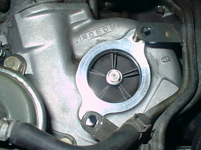
Upgrade Original Turbos
From: "Diep, Anh T" (DIEPAT@sce.com)
$101 each turbo rebuild kit,
$75 each turbo clipping the compressor wheels.
From: Max Cooper (m_cooper@csi.com)
PFS
=================================
* Clip exhaust wheels
* Garrett compressor wheel (T25?)
* ported housing / wastegate porting available
* 45 HP increase at the flywheel
* core required / cracks okay
* 2-3 week turn around
* $2795

Pettit Racing
============================================
OPTION 1:
* balanced and blueprinted
* ceramic coating
* ported compressor housing
* special process to lock compressor wheel nuts
* $650 core / extra charge if core has >8 mm cracks
* ready to ship
* $1695
OPTION 2:
* all the above stuff
* larger compressor wheels (not Garrett)
* 23% more flow
* $2195

Rotary Performance
=========================================
* bigger Garrett compressor wheels
* bigger Garrett shafts for greatly improved reliability at high boost
* trimmed exhaust wheels
* slightly more lag than stock
* pulls strong at high RPM
* 20%-25% better flow, less at lower boost levels
* 8-12 cars on the road with this, at least one running 18 psi for a
year
* Warranty (1 year?)
* 3-4 week turnaround at the present time
* $3100 + core

Turbo Performance Center
===========================================================
OPTION 1/2:
* Garrett T25 or T28 compressor wheels
* 30-35 more HP
* $1900
OPTION 3:
* IHI compressor wheels for significantly lower output temps
* slightly more lag than stock
* ~60 more HP
* 3 cars on the road with this
* $2400
COMMON STUFF:
* TPC has special jigs from Mazda factory reman project
* stock shafts (okay for moderate boost, <18 psi)
* 1 year warranty
* 4-5 day turnaround
* core required / there may be extra charge for really big cracks
From: Max Cooper (m_cooper@csi.com)
From: richardt@lava.net (Richard H Thomason)
Subject: Re: (rx7) [3] why not use upgraded sequential turbo instead of single turbo?
>How much more boost can be run with the greddy upgraded sequential
>turbo system? It would seem to me that if you can run up to 15-18psi of
>boost on this upgraded turbo system, that it would be more efficient than
>a big single turbo.  IE: the sequential system will have less turbo lag.
>The only advantage I can see with a big single turbo is that your boost
>stays the same all the way through the power band, once you've achieved
>full boost, that is.  Whereas the sequential system will still have that
>4500rpm drop?

Aftermarket Turbos
From: William T Wilson (fluffy@snurgle.org)
> reducing turbo lag, or increasing maximum psi that it can produce.
> the psi that it can produce?
> shaft? Can anyone tell me about them and how they can be upgraded,
From: marc.schaefer@am.bnpgroup.com
From: Max Cooper (max@maxcooper.com)
> reducing turbo lag, or increasing maximum psi that it can produce.
> psi that it can produce?
> Can anyone tell me about them and how they can be upgraded, either by
> replacing parts, or replacing the whole thing?
From: "Stephen Ziegler" (SMZ4883@yazaki-na.com)
From: Steven Kan (skan@ticnet.com)
From: Drizzt3117@aol.com
Subject: [mkiv] Single and Twin turbo kits, and their potential (long)
RPS:

TS04:
    Most common housings for this turbo are 0.58 and 0.70, it makes
    about 450 rwhp in the former and 500 rwhp in the latter, spools slightly
    slower than stock, and can commonly be used on the stock fuel system.
    This is a good turbo if you have an automatic, and can be daily driven.

T61:
    Somewhat bigger than the TS04, this turbo can make 550-600 rwhp.  It
    requires an upgraded fuel system.  This doesn't lag too much, a T61 car
    lags a bit more than stock, but is streetable, if not particularly
    responsive, could be used for road racing, not sure if I would recommend
    this turbo for a daily driver.

T66:
    Capable of making 600-675 rwhp, the T66 is a bigger turbo yet, this
    is probably as big a turbo as I would recommend for the street, it makes
    full boost right around 4250 rpm on most cars, a significant amount of
    lag, but not horrendous... (full boost being 1.5-1.6 bar)  This is a very
    common turbo, and a nice setup for drag racing with some street driving.

T70:
    Slightly bigger than the T66, the T70 is probably not a streetable
    turbo. Lag is a couple hundred rpm more than the T66, power output ranges
    from 650-750 rwhp... perhaps a bit more with headwork... This is a nice
    turbo for drag racing.

T72+:
    These turbos are only good for drag cars for the most part, lag is far
    more than smaller turbos, power outputs are from 750-1000 rwhp.Twin turbo
    kit: Using T25/28 ball bearing turbos, this kit will make slightly more
    than 500 rwhp, while spooling faster than the TS04 0.70... very good
    choice for a street car that needs more power than BPU.


HKS:

GT2540:
    These twin turbos are used on the UPRD supra, and used in single form
    on quite a few different cars.  Nice turbos, not enormous lag, maybe slightly
    more lag than their brethren the 2835s, but they spool a little faster
    too... i'm told that car makes power in the 900 rwhp range on turbo alone,
    but this could be just a rumor.

GT2835:
    Probably the most common twin turbos used on supras, this kit is large,
    and the turbos have a fair amount of lag, they make full boost in the 5000
    rpm range, perhaps a bit higher.  Very nice top end on this system, and
    I've seen power output in the 700-800 rwhp range fairly consistently with
    the right fuel support.

T04R:
    A fairly large single turbo, this comes with a pretty big exhaust A/R
    stock, 0.96... I would have thought it would be laggy, but my experience
    with it shows otherwise... it spools a touch faster than a T66, but has a
    bit more power output capability... it has made power in the 675-750 rwhp
    range, and is becoming fairly popular because of this.

T51R:
    This is HKS's biggest single turbo that is commonly sold, although it
    isn't THAT much bigger than the T04R.  Probably in between the T66 and T70
    in size, the T04R makes full boost in the 5k range, and none has really
    been able to realize its full power potential... i wouldn't be surprised
    at seeing 800+ rwhp from a T51R under the right circumstances... very
    strong turbo but i wouldn't use it on a street car personally.


Greddy:

T67:
    The T67 isn't used on supras very often, its a TD07-25g turbo, more
    commonly used on MR2s... its capable of right around 600 rwhp, and spools
    similarly to a T66, so most people choose to go with either the T66 or
    T61.  Again, on the upper limit of streetability.

T78:
    This is one of the more common turbos used on supras... it makes full
    boost somewhat past 5000 rpm, but has the potential to make 750+ rwhp...
    nice turbo, very good top end once it gets spooled... lots of drag cars
    use it, and its fairly inexpensive now.

T88:
    Somewhat bigger than the T78, the T88 has close to 1000 rwhp capability,
    although i would imagine it makes full boost close to 6000 rpm, so a built
    motor is almost a certainty with this turbo... not too expensive but its
    not too usable on most supras so...


Blitz:

Single:
    The Blitz single turbo uses a K27 turbo and is capable of right around
    600-650 rwhp... spools somewhat faster than a T66, and the kit is well
    made, but you need to modify it to work on the US spec supra, pain in the
    ass to do.

Twins:
    Supposedly capable of right around 700 rwhp with about as much lag as
    the single, haven't really heard too much about it to corroborate this,
    but I wouldn't doubt it... kinda of expensive, and this needs heavy
    modification to work on a US spec supra.


Others:

TPC:
    This turbo supposedly has 625-750 rwhp capability with faster spool up
    than a T66... dunno enough about it to really say, but the dyno charts
    seem to show full boost at right around 4500-5000 rpm, which isn't TOO bad
    for a turbo with its power capabilities... not enough people use it to
    really say.


Fastrax:

    Fastrax makes all sorts of custom turbos... my experience with them is
    that they make somewhat more power and spool somewhat faster than the
    turbos they were built off of... fastrax has a lot of experience in the
    drag racing scene, and they make high quality products.  My Fastrax turbo
    supposedly has 750-800 rwhp capability while spooling slightly faster than
    a T66... it certainly spools faster than a T66 in my experience, we'll
    have to see how much it puts down on the dyno.
Date: August 8, 2000
UPRD Sales/Tech
www.uprd.com
877-999-UPRD
From: "Eric Hsu" (dailo502@hotmail.com)
From: "Bernd Kluesener" (bklues@syskonnect.pp.se)
> I have literally been waiting for years for this group to become more
> interested in single T-O4 turbos on 3rd gens.
From: "Jason Baughman" (jbaughman@columbus.rr.com)
From: Aarroneous (aarroneous@pobox.com)
From: "Eric Hsu" (dailo502@hotmail.com)
From: "Jason Baughman" (jbaughman@columbus.rr.com)
From: "Steve Obrien" (poweraxel@peoplepc.com)
From: "Kevin T. Wyum" (aspi@winternet.com)
> > So has anyone tried parallel twins with a new exhaust manifold that
> > pipes each rotor to its own turbo?  In other words, instead of one big
> > turbo, you run two small turbos completely in parallel.  Does anyone
> > know if a different exhaust manifold would make parallel twin
> > performance more acceptable?
>
>Someone has, I want to say Trev D. did this a long time ago.
>I believe that Jim LaBreck is the custodian of that information.
>
>The manifold would definitely have to be designed and a set of turbos
>selected.  I think the problem here, is that it would cost more to buy 2 smaller turbos
>than one medium one.  I don't know how much better low-end would be, ala do you
>get instant boost at 3k/rpms like stock.  Maximum boost doesn't offer any hardcore
>math to calculate the things I thought it did -- you'll need to get a hold of some SAE
>papers and maybe some other references to work out the math.
>
>The Supra guys do this, not sure how well it performs compared to a single turbo.
    Dear Mr. Wyum:

    Acount # phonenumber here

    Thank you for sending in the check. Put as far as our accounts go your account
    has been closed for quite sometime. So inclosed is your check.

    Thank You,

    Carolyn Thompson"
Turbo Manifold
From: Steve OBrien (poweraxel@peoplepc.com)
From: James T Fredericks (jfrederi@juno.com)
> I'm going to need to have a manifold made.  I would like to have a
> Stainless steel one made.  I understand there is a shop or person in
> Florida that does this type of stuff.
From: richardt@lava.net (Richard H Thomason)
From: richardt@lava.net (Richard H Thomason)
From: "Steve OBrien" (poweraxel@peoplepc.com)
Turbo Vacuum Hose Replacement
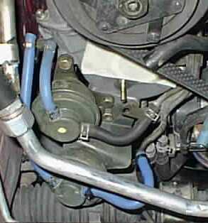
From: "Mike Putnam" (mike_putnam@hotmail.com)
>And McMaster-Carr also have small Viton tubing, which is
>probably the best alternative for the vacuum hose replacement job,
>though it costs more.
From: "Nicholas Riefner"
From: Dana Bourgeois
From: "Mike Putnam" (mike_putnam@hotmail.com)
Subject: (rx7) Re:[3] Vacuum Hose, Silicone vs. Fluorine
SILICONE TUBING
Operating temp -60 F to 460 F
Resistant to oil grease and solvents
Durometer Shore A hardness of 50
   kink resistance - fair
   abrasion and cut resistance - poor
Due to a lack of abrasion/cut resistance tie-wraps
   or glue are recommended for securing.
   (Unfortunately, the highest service temperature
   for tie-wraps is below 200 F.
Widely available, comes in many colors
Cost (from tubing/hose supply catalog) $1/ft

FLUORINE RUBBER TUBING
(Sold under various trade names such as Viton, Fluran, etc.
I think that Pettit sells Goodyear's version of this tubing)
Operating temp -25 F to 400 F
Resistant to oil grease and solvents
Durometer Shore A hardness 60
   kink resistance - good
   abrasion and cut resistance - good
Spring clamps can be used for securing. ($0.20/clamp at Home Depot)
Comes only in black
Not available at most auto supply stores/catalogs
Cost (from tubing/hose supply catalog) $1.44/ft
From: "Mike Putnam" (mike_putnam@hotmail.com)
Subject: Re: (rx7) Re:[3] Vacuum Hose, Silicone vs. Fluorine
>seems to soften over time.
48 HOUR RATING SCALE
A- no effect
B- minor effect
C- moderate effect
D- severe effect

Chemical      Flourine Rubber        Silicone
Gasoline            B                   C
Motor Oil           B                   C
Synthetic Oil       A                   B
Sperm Whale Oil     A                   A
--Steve
Baker Precision
2865 Gundry Ave.
Signal Hill, CA 90806 USA
800 - 959 - 7757
562 - 427 - 2375
Fax 562 - 426 - 5294
From: Spencer Hutchings
From: EDRX7
EM097 FD3S (3rd gen RX-7) hose replacement kit (red) $44
EM091 Silicone hose (blue) 4mm $1.00/foot
EM092 Silicone hose (yellow) 4mm $1.25/foot
EM093 Silicone hose (red) 4mm $1.25/foot
EM094 Silicone hose (blue) 6mm $1.50/foot
EM095 Silicone hose (yellow) 6mm $1.75/foot
EM096 Silicone hose (red) 6mm $1.75/foot
Silicone hose joint 2 1/4" $4/inch
Silicone hose joint 2 1/2" $4.50/inch
Silicone hose joint 2 3/4" $5/inch
vacuum hose kit $45.00 total
includes:	14' 4mm hose blue
            10' 6mm hose red
            100 4" tie wraps
From: EDRX7
Date: Friday, March 03, 2000 5:33 AM
3.5mm ID, 40 feet:  fits all the small vacuum lines under and over
                    the intake manifold and extra feet for
                    aftermarket boost controllers.
4.0mm ID, 15 feet:  Windshield Washers.
6.0mm ID. 16 feet:  Intake manifold and radiator overflow and there
                    is extra hose for aftermarket boost controllers.
8.0mm ID,  4 feet:  other locations as necessary.
From: rotary@mediaone.net (Carlos Iglesias)
>I also wondered about the possibility of the silicone
>tubing collapsing or being pinched. The stock lines
>are preformed and much stiffer than the silicone lines.
>The silicone lines can be collapsed very easily.
From: "Westbrook, Chuck"
> plastic zip ties or actual wire like they use in racing to hold bolts in
> place?
From: Max Cooper
Date: 03/01/2002 03:31 PM
From: dbeale (dbeale@harddata.com)
Material                  Temp Range
Nylon                    -40 to +185 F
Flame retardant Nylon    -40 to +203 F
TEFZEL                   -50 to +302 F
HALAR                    -50 to +284 F
Nylon 12                 -40 to +176 F
Polyproylene             -40 to +185 F
From: Wael El-Dasher (wael.el-dasher@efini.net)
Part number: 9928-30-800
size:        8mm (3/8") for use with 4mm (ID) vacuum hoses
price:       $.65/ea. ($1.10/ea.from dealer!)
source:      Mazda Comp
Turbo Pipe Kit
From: "Jeff Witzer"
> turbo and the intercooler piping. I always want an aftermarket one
> from long time ago, but there's no one making it.
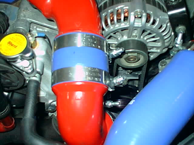
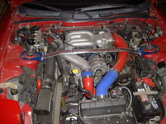
"Y" Turbo Outlet Duct (Efini Y-pipe)
From: "Westbrook, Chuck"
From: "Westbrook, Chuck"
From: brad barber (bradrx7@bradbarber.com)
> I thought the reason people use the Efini Y-pipe is to eliminate the
> coupler?  If you cut off the flange and welded a bead, then used a hose to
> connect it to the ASP pipe, wouldn't you be left with essentially the same
> setup as stock?  Are there other differences with the Efini pipe other than
> the flange and "flat" metal tube?
From: GDK (gdolittle@postoffice.worldnet.att.net)
> outlets AND the pipe running from there to the intercooler?
> intercooler more reliable than the OEM rubber hose?
From: "Westbrook, Chuck E." (CWestbrook@tmh.tmc.edu)
From: "Ryan Schlagheck" (ryan.schlagheck@worldnet.att.net)
From: "kevin kelleher" (kellehkj@earthlink.net)
Blow-Off Valves
From: "Jim LaBreck" (jimlab@earthlink.net)
From: "Jim LaBreck (ECA)" (a-jimlab@microsoft.com)
From: "David H. Lane" (dlane@peabody.jhu.edu)
From: "Kevin T. Wyum" (aspi@winternet.com)
From: NetBlazer (netb@world.bc.ca)
article
on performance myths:
From: "Westbrook, Chuck" (CWestbrook@tmh.tmc.edu)
From: "Fritz McKellar" (sico@cyberus.ca)
From: "Westbrook, Chuck E." (CWestbrook@tmh.tmc.edu)
Subject: RE: (rx7) (all) BOV location
From: RudylRx7@aol.com
Boost Unit Conversion
From: "Westbrook, Chuck E." (CWestbrook@tmh.tmc.edu)
One ATM      is equal to 14.7 PSI.

One Kg/Cm^2  is equal to 14.2 PSI.

One BAR      is equal to 14.5 PSI.
Boost Control
>other turboed cars?
From: "kevin kelleher" (kellehkj@earthlink.net)
From: "Sandy Linthicum" (sandy-linthicum@nc.rr.com)
Subject: RE: (rx7) [3] Boost Levels at High Elevations
> As far as I understand, if I am at 5500 ft., I can run "higher
> boost" by 2.7 psi, and still have the same absolute boost level if
> compared to sea level.  However, oxygen levels become lower with
> altitude.  So is it really safe to run "more boost" at higher
>Depends on sensor used to measure pressure.  If map sensor is a
>load cell type that is sealed with no outlet to ATM then 12psi
>measured in the manifold is 12psi at sea level or in space.
>Gas may be lower octane but 93 octane is still 93 regardless of
>altitute
>Intake may be cooler since inlet air would generally be colder.
>On the other hand, a lot more RPM is necessary at the turbo
>compressor due to thinner air.
From: "Westbrook, Chuck E." (CWestbrook@tmh.tmc.edu)
Subject: (rx7) [3] how boost is controlled
From: David Liberman (liberman@scott.net)
>pre-control all differ. My guess is that the wastegate controls exhaust
>volume to both turbos, the pre-control controls exhaust to the secondary
>turbo separately and I have no idea what the turbo control does but it
>appear to be separate from the wastegate.
From: Brooks Weisblat (brooks@miamisci.org)
HKS 1404-RA005		Adjustable pop-off valve
			12-18 pounds
HKS 08108-09159		Flange
HKS 17678-001100	Gasket
From: Brooks Weisblat (brooks@miamisci.org)
From: Brooks Weisblat (brooks@miamisci.org)
From: Rippin (rippin@pottsville.infi.net)
> or the turbo precontrol line? My understanding (which I believe is correct)
> is that the precontrol is essentially the wastegate for the 1st turbo. Once
> max boost is reached on turbo 1, the precontrol begins opening, which bleeds
> exhaust pressure to the second turbo to pre-spool it. At this point, the
> wastegate control is doing little, if anything. Then, once the turbo
> control valve flips the big exhaust door open, exhaust gas is evenly divided
> to spin both turbos. At this point the wastegate control valve is used to
> bypass both turbos and bleed exhaust pressure.
>
> Thus, a manual valve in the precontrol line only affects boost levels when
> operating on the 1st turbo. If a valve is in the wastegate line, it will
> only control boost when operating in dual turbo mode. If my understanding
> is incorrect, please correct me. However, this is how Cam at Pettit
> explained it (or at least how I understood it), and it makes sense;
> especially when you consider that the precontrol & wastegate diaphragms and
> solenoids are essentially identical and have the exact same hose routing.
> They just connect to different control doors in the turbo assembly.
>
> So, to really control boost effectively you need to install separate manual
> valves in the precontrol & wastegate lines, correct? Is anyone on the list
> running this kind of setup, or has anyone tried it?
From: "Westbrook, Chuck E." (CWestbrook@tmh.tmc.edu)
> I have the "Home Depot" manual boost control.  Ive been running this mod
> for about 2 months and it is effective.  However, I have not disabled the
> control solenoid and have been told that others do.  Can someone with this
> mod- or knowledge of it, let me know if I should disable the wastegate
> control solenoid.
From: "Emilio G. Littel" (emilio@littel.com)
ABBT = Average Boost Before Transition.
SBT  = Spike Before Transition.
SAT  = Spike After Transition.
ABAT = Average Boost After Transition.
Valve listings are number of turns from closed.

Combo#    Pre-Control Valve    Wastegate Valve     ABBT      SBT       SAT      ABAT
    1            3.25                2.75           8.7     10.2      10.2       8.7
    2            3.5                 2.75           8.7      8.7      11.6       9.1
    3            3.75                2.5            8.7     10.2       8.7       8.7
    4            3.75                3              8.7     10.2      10.2       8.7
    5            3.875               3.25           8.7     12.0       8.7       8.0
    6            3.875               3.5            8.7     10.2       9.4       8.7
    7            3.875               4              8.7     10.2       8.7       7.3
    8            4                   4              7.3      8.0       8.0       7.3
From: TAKESHI988@aol.com
          (conncted by hose)
  turbo-------------------------> input of t.v.v.c----->some mechanism which
restricted

air flow---------> output of t.v.v.c------------------------>wastegate
actuator
                                               (connected by hose)
From: NetBlazer (netb@core.bisc.com)
Subject: (rx7) [3] stock waste-gate orfice
From: "Westbrook, Chuck" (CWestbrook@tmh.tmc.edu)
From: "Westbrook, Chuck E." (CWestbrook@tmh.tmc.edu)
Subject: (rx7) [3] Hallman Manual Boost Control Intall And Results
Pills To Control Boost
From: Max Cooper (max@maxcooper.com)
From: Tuck
From: brad barber
> ... adjusting boost by screwing with the pills is idiotic.
> cheaply as possible, mount a manual boost controller (which is basically
> just a knob-adjustable valve) for each of them in the cockpit. You'll
> retain the relatively quick response of the wastegates with the stock
> pills, and making the adjustments you want will be much easier.
From: Tuck
From: brad barber (bradrx7@swbell.net)
> PFS PMC, you can just use control the stepper motor vent (HKS) or solenoids
> (PMC), and that is the right way to do it because wastegate response will
> remain fast and reliable. It's also about a thousand times more convenient
> than screwing with pills and hoses.
From: Tuck (sldbrass@darksideresearch.com)
From: brad barber
From: "Jones, Trey" (Trey.Jones@COMPAQ.com)
From: "Jones, Trey" Trey.Jones@COMPAQ.com
From: "Nick Riefner" (racin@worldnet.att.net)
From: Tuck (sldbrass@darksideresearch.com)
>I don't pretend to fully understand the turbo system on the 3rds, but could
>you explain how manual boost control valves would be different from
>changing the pills?  Wouldn't this give the same effect of varying the size
>of the aperature in the lines?  Just a different way of achieving it?
From: Rob Robinette (robinett@postoffice.dca.net)
From: "Jones, Trey" (Trey.Jones@COMPAQ.com)
From: "Westbrook, Chuck" (CWestbrook@tmh.tmc.edu)
From: "Westbrook, Chuck" (CWestbrook@tmh.tmc.edu)
From: brad barber (bradrx7@swbell.net)
Pre-control (longer hose) .059"
Wastegate (shorter hose) .064"
From: "albeder" (albeder@earthlink.net)
07/16/98
pre-control (long) .059"
wastegate (short) .064"
40  .040  |  61  .060  |  81  .093
41  .041  |  62  .061  |  82  .093
42  .042  |  63  .062  |  83  .094
43  .043  |  64  .064  |  84  .099
44  .044  |  65  .065  |  85  .100
45  .045  |  66  .066  |  86  .101
47  .047  |  67  .068  |  87  .103
48  .048  |  68  .069  |  88  .104
49  .048  |  69  .070  |  89  .104
50  .049  |  70  .073  |  90  .104
51  .050  |  71  .076  |  91  .105
52  .052  |  72  .079  |  92  .105
53  .052  |  73  .079  |  93  .105
54  .053  |  74  .081  |  94  .108
55  .054  |  75  .082  |  95  .118
56  .055  |  76  .084  |  96  .118
57  .056  |  77  .086  |  97  .125
58  .057  |  78  .089  |  98  .125
59  .058  |  79  .091  |  99  .125
60  .060  |  80  .093  | 100 .128
From: "Westbrook, Chuck" (CWestbrook@tmh.tmc.edu)
From: Max Cooper (max@maxcooper.com)
From: KELLEHKJ@ESVAX-MAIL.ES.DUPONT.COM
>boost spike problem I've got
From: e s (rx712psi@yahoo.com)
Subject: Re: (rx7) (RX-7)(3)Check Valves
From: Daegal Benedetto (dae@ix.netcom.com)
From: "Bernd Kluesener"
RPM     ABS. CUT OFF(PSI)       SEA LEVEL CUT OFF(PSI)

1000    26.5                    11.8
1500    26.5                    11.8
2000    26.5                    11.8
2500    26.5                    11.8
3000    26.9                    12.2
3500    27.1                    12.4
4000    27.5                    12.8
4500    28.0                    13.3
5000    26.9                    12.2
5500    26.0                    11.3
6000    25.8                    11.1
6500    25.4                    10.7
7000    25.4                    10.7
Turbo Manifold Cracking
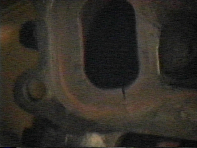
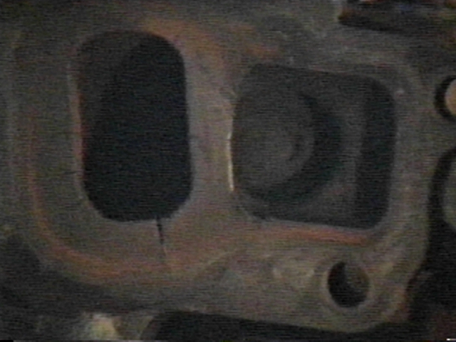
Wastegate Porting
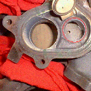
>I have a set of freshly rebuilt turbos that I have not
>installed yet, and am thinking of pulling the snails
>off to do some port matching, and porting of the
>wastegate opening.
>
>Majestic did some boring of the bottom end of the
>wastgate, but the lip where the flapper closes remains
>untouched.
>
>Would it be worth my time to do the porting?  Is it
>impossible to get the oil passages aligned correctly
>when re-installing the snails?
>
>If anyone out there has any experience with this could
>you please give me some pointers & advice?
Stock Wastegate Adjustment
> wastegate adjustment. This question is kind of outside of the usual
> discussion on boost control, as it would need to be a factory or dealer
> type adjustment in order to be legal in the autox stock class.
>
> Is there any way to adjust the boost w/o modifying the control system?
> i.e.- adjustment screws, etc? Adding anything to, or re-plumbing, the
> vacuum system would not be legal.
Date: July 8, 1999
Date: July 9, 1999
via: Carlos A. Iglesias (rotary@san.rr.com)
Sent: 09 July, 1999 23:11 PM
From: "Ulen, Robert S" (Robert.Ulen@PSS.Boeing.com)
Turbo Timer
Turbo Pre-Luber (Pre-oiler)
> I got "0" responses to this post.  I guess everyone has turbo timers.
> The pre-luber is more expensive but I like that it brings up pressure
> before you start and pumps the oil up to 5 minutes after you shut down.
> I went ahead and ordered it. It was $489.00 plus shipping.  I'm getting
> it because I'm rebuilding the turbos on my car which has 31k on the
> clock and is only used for street use. Here's the web site if you want
> to take a look : www.enginelube.com.
> Let me know what you think,
From: Sandy Linthicum
From: F8LDZZ
Water Injection
From: zgluszek@VNET.IBM.COM
Water Injection - It lets you safely develop
more power with nearly no running costs!
by Julian Edgar
How it Works
Always Water?
From: "Kevin T. Wyum" (aspi@winternet.com)
Date: September 9, 1999
Date: February 7, 2001
>Yes, you now have to add water when you get gas, and it is
>one more thing to go wrong, but the Aquamist 2s system has built in
>diagnostic sensors (blocked fluid flow, cut hoses, etc.) to make sure
>you don't boost if there's a problem.  But think of this:
>1) Depending on power levels desired, you can stay with the
>stock injectors and computer.  This can be a big savings for
>those who add a downpipe, intake, and cat-back, and want to
>make sure they're not going to detonate.
>2) Turbo's will last longer, due to 50-100F lower exhaust temp.
>3) Savings at the gas pump, because the leaner mixture
>increases BSFC.  I like this one...  :-)
Miscellaneous
From: "Cassada, Lewis" (LCassada.dit@state.va.us)
From: tom (jelkil@interaccess.com)